
Subscribe to Our Youtube Channel
Related Manuals for Kramer VSM-4x4A


Summary of Contents for Kramer VSM-4x4A
- Page 1 USER MANUAL MODEL: VSM-4x4A 4x4 Seamless AV Matrix Switcher/Multi-Scaler P/N: 2900-300668 Rev 2 www.KramerAV.com...
-
Page 6: Table Of Contents
VSM-4x4A RS-232/Ethernet Communication Protocol 10.1 Understanding Protocol 3000 10.2 Kramer Protocol 3000 Syntax 10.3 Protocol 3000 Commands Figures Figure 1: VSM-4x4A 4x4 Seamless AV Matrix Switcher/Multi-Scaler Front Panel Figure 2: VSM-4x4A 4x4 Seamless AV Matrix Switcher/Multi-Scaler Rear Panel VSM-4x4A – Contents... - Page 7 Figure 3: Connecting the VSM-4x4A Presentation Switcher / Scaler Figure 4: VSM-4x4A Video Wall Operation Mode Figure 5: Connecting the VSM-4x4A in 2x2 Video Wall Operation Mode Figure 6: Connecting the VSM-4x4A in 1x4 Video Wall Operation Mode Figure 7: VSM-4x4A Bezel Correction...
-
Page 8: Introduction
GROUP 10: Mounting and Rack Adapters; GROUP 11: Sierra Video; GROUP 12: Digital Signage; GROUP 13: Audio; GROUP 14: Collaboration; and GROUP 15: KM & KVM Switches. Congratulations on purchasing your Kramer VSM-4x4A 4x4 Seamless AV Matrix Switcher/Multi-Scaler. The VSM-4x4A incorporates HDMI™ technology and is ideal for: ... -
Page 9: Getting Started
Avoid interference from neighbouring electrical appliances that may adversely influence signal quality Position your Kramer VSM-4x4A away from moisture, excessive sunlight and dust This equipment is to be used only inside a building. It may only be connected to other equipment that is installed inside a building. -
Page 10: Safety Instructions
Kramer Electronics has made arrangements with the European Advanced Recycling Network (EARN) and will cover any costs of treatment, recycling and recovery of waste Kramer Electronics branded equipment on arrival at the EARN facility. For details of Kramer’s recycling arrangements in your particular country go to our recycling pages at www.kramerav.com/support/recycling/. -
Page 11: Overview
Overview The VSM-4x4A is a 4x4 seamless matrix switcher that can also be used as a video wall driver (2x2 or 1x4) or dual and quad multi-viewers. The unit enables switching between inputs with a clean video cut (frame-to-frame switching with no glitches). -
Page 12: Defining The Vsm-4X4A
Via the Ethernet with built-in Web pages The VSM-4x4A is housed in a 19” 1U rack mountable enclosure, with rack ears included, and is fed from a 100-240 VAC universal switching power supply. Defining the VSM-4x4A This section defines the VSM-4x4A. -
Page 13: Figure 1: Vsm-4X4A 4X4 Seamless Av Matrix Switcher/Multi-Scaler Front Panel
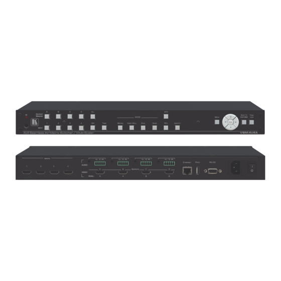
Figure 1: VSM-4x4A 4x4 Seamless AV Matrix Switcher/Multi-Scaler Front Panel Feature Function IR LED Lights when the unit accepts IR remote commands IR Receiver Receives signals from the remote control transmitter OUTPUT/WINDOW In the MATRIX mode: select the output to which the input is switched (A, B, C or D) -
Page 14: Figure 2: Vsm-4X4A 4X4 Seamless Av Matrix Switcher/Multi-Scaler Rear Panel
Press and hold for about 4 seconds to toggle resetting the video resolution to XGA or 1080p Button PANEL LOCK Button Press and hold for about 2 seconds to lock/unlock the front panel buttons Figure 2: VSM-4x4A 4x4 Seamless AV Matrix Switcher/Multi-Scaler Rear Panel Feature Function INPUT HDMI Connectors Connect to the HDMI sources (from 1 to 4) AUDIO OUTPUT 3.5mm Mini Jack... -
Page 15: Installing In A Rack
Installing in a Rack This section provides instructions for rack mounting the unit. VSM-4x4A – Installing in a Rack... -
Page 16: Connecting And Operating The Vsm-4X4A
You can select the different operation modes via front panel buttons, the IR remote control transmitter and OSD menu or via the Web pages. This section describes how to connect and operate the VSM-4x4A in each of the four operation modes. -
Page 17: Matrix Mode
Matrix Mode The VSM-4x4A matrix switcher mode is the default operation mode. Any of the four inputs can be switched to any of the four outputs. Switching is immediate and seamless. 5.1.1 Connecting the VSM-4x4A in Matrix Mode To connect the VSM-4x4A in Matrix mode, as illustrated in the example in Figure 1. -
Page 18: Video Wall Mode
Each output shows one quarter of the image as shown in the example in Figure In Video Wall mode, the audio of the selected input is routed to one of the outputs. Figure 4: VSM-4x4A Video Wall Operation Mode 5.2.1 Connecting the VSM-4x4A in Video Wall Mode... -
Page 19: Figure 5: Connecting The Vsm-4X4A In 2X2 Video Wall Operation Mode
A PC via RS-232, see Section 6 .4 The ETHERNET port, see Figure 5 shows a 2x2 video wall layout: Figure 5: Connecting the VSM-4x4A in 2x2 Video Wall Operation Mode VSM-4x4A – Connecting and Operating the VSM-4x4A... -
Page 20: Figure 6: Connecting The Vsm-4X4A In 1X4 Video Wall Operation Mode
Figure 6 shows a 2x2 video wall layout: Figure 6: Connecting the VSM-4x4A in 1x4 Video Wall Operation Mode 5.2.2 Operating the VSM-4x4A in Video Wall Mode To select the inputs via the front panel buttons/IR remote control transmitter: 1. Press VIDEO WALL on the front panel to select the Video Wall operation mode. -
Page 21: Figure 7: Vsm-4X4A Bezel Correction
In the example in Figure 7 the top photo shows the video wall before bezel correction and the lower photo shows the corrected image on the video wall. Figure 7: VSM-4x4A Bezel Correction VSM-4x4A – Connecting and Operating the VSM-4x4A... -
Page 22: Dual Mode
Dual Mode In Dual mode, VSM-4x4A is set as a 4x2 switcher with picture-in-picture capabilities that outputs two identical A outputs and two identical B outputs (see Figure The dual outputs display any two selected input signals together on one screen. -
Page 23: Figure 8: Connecting The Vsm-4X4A In Dual Operation Mode
In the following example, “Show” is selected in the BORDER menu Section 6 item (see .2.1) to display all the borders. Figure 8: Connecting the VSM-4x4A in Dual Operation Mode 5.3.2 Operating the VSM-4x4A in Dual Mode To select the inputs via the front panel buttons/IR remote control transmitter: 1. -
Page 24: Quad Mode
Figure 9: the VSM-4x4A QUAD Operation Mode Input Orientation 5.4.1 Connecting the VSM-4x4A in Quad Mode To connect the VSM-4x4A in Quad mode as illustrated in Figure 1. Connect an HDMI source to up to four inputs, not shown in Figure 2. -
Page 25: Figure 10: Connecting The Vsm-4X4A In Quad Operation Mode
.2.1) to display only the border of the selected output. All four inputs are displayed on each of the output displays. 5.4.2 Operating the VSM-4x4A in Quad Mode Press QUAD on the front panel to operate the VSM-4x4A in Quad Mode. VSM-4x4A – Connecting and Operating the VSM-4x4A... -
Page 26: Wiring The Rj-45 Connectors
Blue / White Green Brown / White Brown Connecting the Balanced Stereo Audio Line Output Figure 12: Connecting the Balanced Figure 13: Connecting an Unbalanced Stereo Audio Output Stereo Audio Acceptor to the Balanced Output VSM-4x4A – Connecting and Operating the VSM-4x4A... -
Page 27: Controlling The Vsm-4X4A
RESET TO XGA/720p and PANEL LOCK buttons 6.1.1 Switching Inputs to Outputs Inputs are routed to outputs differently for each of the four operation modes. Incomplete operations on the VSM-4x4A timeout after 15 seconds. VSM-4x4A – Controlling the VSM-4x4A... - Page 28 The selected button illuminates. 2. Press an INPUT button (from 1 to 4) to select the left/main image on the output. 3. Press an INPUT button (from 1 to 4) to select the right/PIP image on the output. VSM-4x4A – Controlling the VSM-4x4A...
- Page 29 6.1.1.2 Disconnecting an Input from an Output To disconnect an input from an output: 1. Press the required OUTPUT button (A to D). The selected output Illuminates. 2. Press OFF. The selected output is disconnected. VSM-4x4A – Controlling the VSM-4x4A...
- Page 30 Every action requires user confirmation which protects against erroneous switching Execution is delayed until the user confirms the action If the TAKE button is not pressed within 60 seconds, this action is aborted. VSM-4x4A – Controlling the VSM-4x4A...
- Page 31 INPUT buttons. The stored setups are saved in the non-volatile memory. Note that you can also store and recall a setup via the OSD menu (see Section 6 Section 7 .2.1) and the Web pages (see VSM-4x4A – Controlling the VSM-4x4A...
- Page 32 (OUTPUT A to OUTPUT D) to select the audio source Muting the audio output – Press and hold the ALL button (for 3 seconds) to toggle between muting (blocking out the sound) and enabling the audio output VSM-4x4A – Controlling the VSM-4x4A...
-
Page 33: Using The Osd Menu
Using the OSD Menu Use the front panel control buttons to control the VSM-4x4A via the OSD menu. Press: MENU to enter the menu The default timeout is set to 10 seconds ENTER to accept changes and to change the menu settings ... - Page 34 In QUAD Mode Set the CONTRAST, BRIGHTNESS, SATURATION and HUE separately for QUAD 1, QUAD 2, QUAD 3 and QUAD 4 RESET each parameter for all the QUADs RESET ALL the PICTURE parameters to their default values VSM-4x4A – Controlling the VSM-4x4A...
- Page 35 Note that output resolutions 480p and 576p do not support bezel correction Note that the 1x4 video wall setup supports V BEZEL correction only IDENTIFY Identify each input/output as well as the audio source (for DUAL and QUAD modes) VSM-4x4A – Controlling the VSM-4x4A...
- Page 36 VIDEO OUT B RIGHT: IN 1, IN 2, IN 3 or IN 4 Set the audio source for outputs A and outputs B (left or right for each set): AUDIO OUT A: LEFT or RIGHT AUDIO OUT B: LEFT or RIGHT VSM-4x4A – Controlling the VSM-4x4A...
- Page 37 Use STORE to store the current setup to one of the four memories (FAV. 1 to FAV. 4) Use RECALL to select a stored setup NOW (current status) shows the current setup for all four outputs VSM-4x4A – Controlling the VSM-4x4A...
- Page 38 Set the IP, MASK and GATE addresses via these 4 bytes By default: IP = 192.168.1.39; Gateway = 192.168.1.254; and Netmask = 255.255.255.0 NOW shows the current link status and the current IP, MASK and GATE addresses VSM-4x4A – Controlling the VSM-4x4A...
- Page 39 Lock the MENU (and navigation) front panel buttons only ALL & SAVE Lock all the front panel buttons The lock status is saved when the VSM-4x4A is powered down MENU ONLY & SAVE Lock the MENU (and navigation) front panel buttons only The lock status is saved when the VSM-4x4A is powered down VSM-4x4A –...
-
Page 40: Connecting To The Vsm-4X4A Via
Kramer logo Connecting to the VSM-4x4A via RS-232 You can connect to the VSM-4x4A via an RS-232 connection using, for example, a PC. Note that a null-modem adapter/connection is not required. To connect to the VSM-4x4A via RS-232, connect the RS-232 9-pin D-sub rear panel port on the product unit via a 9-wire straight cable (only pin 2 to pin 2, pin 3 to pin 3, and pin 5 to pin 5 need to be connected) to the RS-232 9-pin D-sub port on your PC. -
Page 41: Operating The Vsm-4X4A Via Ethernet
6.4.1 Connecting the Ethernet Port Directly to a PC You can connect the Ethernet port of the VSM-4x4A directly to the Ethernet port on your PC using a crossover cable with RJ-45 connectors. This type of connection is recommended for identifying the VSM-4x4A with the factory configured default IP address. -
Page 42: Figure 14: Local Area Connection Properties Window
4. Highlight either Internet Protocol Version 6 (TCP/IPv6) or Internet Protocol Version 4 (TCP/IPv4) depending on the requirements of your IT system. 5. Click Properties. The Internet Protocol Properties window relevant to your IT system appears as shown in Figure 15 Figure VSM-4x4A – Controlling the VSM-4x4A... -
Page 43: Figure 15: Internet Protocol Version 4 Properties Window
Figure 15: Internet Protocol Version 4 Properties Window Figure 16: Internet Protocol Version 6 Properties Window VSM-4x4A – Controlling the VSM-4x4A... -
Page 44: Figure 17: Internet Protocol Properties Window
8. Click Close. 6.4.2 Connecting the Ethernet Port via a Network Hub or Switch You can connect the Ethernet port of the VSM-4x4A to the Ethernet port on a network hub or using a straight-through cable with RJ-45 connectors. 6.4.3... -
Page 45: Controlling Via The Ir Remote Control
Controlling via the IR Remote Control You can control the VSM-4x4A from the infrared remote control transmitter: Keys Function POWER Toggle the power save mode ON or OFF IDENTIFY Identify the inputs on each output INFO Indicate on each output, which... -
Page 46: Using The Ir Remote Control In Dual Mode
Figure 19 shows the remote control with dual mode operation instructions. Note that these instructions are further detailed in the following pages. Figure 19: IR Remote Control Transmitter Dual Mode Shortcuts VSM-4x4A – Controlling the VSM-4x4A... - Page 47 POP B: press OUT C/OUT D to select the Left/Right window for B (f) 2. Select the input to switch to the output: Press one of the inputs (IN 1 to IN 4) to switch to the selected output (g) For PIP/POP A: VSM-4x4A – Controlling the VSM-4x4A...
- Page 48 POP A: press AUDIO 1/AUDIO 2 to select the Left/Right audio source for A POP B: press the AUDIO 3/AUDIO 4 to select the Left/Right audio source for B (i) For PIP/POP A: For PIP/POP B: VSM-4x4A – Controlling the VSM-4x4A...
- Page 49 Press up/down arrow to select the PIP window size (l) Press the left/right arrow to select the PIP window position (m) Press the OK button to swap between main and PIP windows (n) VSM-4x4A – Controlling the VSM-4x4A...
-
Page 50: Firmware Upgrade
Firmware Upgrade You can upgrade the VSM-4x4A via the USB port on the rear panel or via the Section 8 Device Settings web pages (see .3.2). The latest firmware version can be downloaded from the Kramer Web site at www.kramerav.com/downloads/VSM-4x4A. -
Page 51: Using The Embedded Web Pages
Using the Embedded Web Pages The Web pages let you control the VSM-4x4A via the Ethernet. The Web pages include all the OSD items and more, and are accessed using a Web browser and an Ethernet connection. Before attempting to connect: ... -
Page 52: Routing & Scaling Page
The list of Web pages appears to the left of each page. Click a page from the list to open it. VSM-4x4A includes seven Web pages: Section 8 The Routing & Scaling page (see Section 8 The Device settings page (See ... -
Page 53: Figure 21: The Matrix Tab Output Resolution (Seamless Mode)
Select one of the following switching configurations: Click Seamless for zero-time switching (resolution on all the outputs is the same) and select the resolution from the drop-down list Figure 21: The Matrix Tab output Resolution (Seamless Mode) VSM-4x4A – Using the Embedded Web Pages... -
Page 54: Figure 22: Matrix Tab Output Resolution (Independent Mode)
The Output buttons show the resolution and the input buttons show the signal type (or NO SIGNAL in this example). To switch an Input to an Output in the Matrix Mode: 1. Click an output. 2. Click an input button to switch to that output. VSM-4x4A – Using the Embedded Web Pages... -
Page 55: Figure 23: 2X2 Video Wall Tab
Click Video Wall to display the Video Wall mode window and select either a 2x2 (see Figure 23) or a 1x4 (see Figure 24) wall: Figure 23: 2x2 Video Wall Tab Figure 24: 1x4 Video Wall Tab VSM-4x4A – Using the Embedded Web Pages... -
Page 56: Figure 25: The Video Wall Tab - Bezel Correction
Crop and Position the Image Section 5 Crop and/or position the image on the 1x4 video wall (see .2) via the Video Wall tab: Figure 26: The Video Wall Tab – Crop/Position Correction VSM-4x4A – Using the Embedded Web Pages... -
Page 57: Figure 27: The Dual Tab - Pop Mode
POP – Side-by-side images on the output (Left and Right) Figure 27: The Dual Tab – POP Mode PIP – A PIP image over the main image on the output Figure 28: The Dual Tab – PIP Mode VSM-4x4A – Using the Embedded Web Pages... -
Page 58: Figure 29: The Dual Tab - Pip Position And Size
For POP: select the Left or Right on the A or B outputs For PIP: select the MAIN or PIP on the A or B outputs Click an input button to switch to the output. VSM-4x4A – Using the Embedded Web Pages... -
Page 59: Figure 30: The Quad Tab
Section 8 Store and recall a configuration (see .2.5) Set the borders of an image to Show, Only Selected or Off Set the output resolution via the resolution drop-down box VSM-4x4A – Using the Embedded Web Pages... -
Page 60: Figure 31: The Matrix Tab - Store A Configuration
8.2.5.1 Editing the Input Window Click the edit icon to edit the input button. This window lets you edit the input label: Figure 33: Matrix Tab – Input Edit Window VSM-4x4A – Using the Embedded Web Pages... -
Page 61: Figure 34: The Matrix Tab - Typing The New Label
Label. The following message appears: Click OK to save the label name. Toggle to view the label in the Web pages: Figure 35: The Matrix Tab – Viewing the Label Click to exit the input editing window. VSM-4x4A – Using the Embedded Web Pages... -
Page 62: Device Settings Page
The Device Settings page (in Figure 36) displays the firmware version and lets you set the Ethernet parameters, perform a factory reset and show the information window. Figure 36: The Device Settings Page VSM-4x4A – Using the Embedded Web Pages... -
Page 63: Figure 37: The Device Settings Page - Ethernet Settings
When changing the IP address, the change is immediate and the Web page reloads with the new IP address (see Figure 38). Figure 37: The Device Settings Page – Ethernet Settings Figure 38: The Device Settings Page – IP Number Settings VSM-4x4A – Using the Embedded Web Pages... -
Page 64: Figure 39: Device Settings Page - Information Window
To view the device information, click the icon on the lower right side of the page. Figure 39: Device Settings Page – Information Window VSM-4x4A – Using the Embedded Web Pages... -
Page 65: Figure 40: Device Settings Page - Uploading The Firmware File
1. Click Browse and select the file. Figure 40: Device Settings Page – Uploading the Firmware File 2. Click Start Upgrade. The following window appears: Figure 41: Device Settings Page – Firmware Upgrade Message VSM-4x4A – Using the Embedded Web Pages... -
Page 66: Figure 42: Device Settings Page - Firmware Upgrade Complete
4. Reboot the device and then refresh the Web page. 8.3.3 Factory Reset Click Soft Factory Reset to reset the device. The following message appears: Figure 43: The Device Settings Page – Factory Reset Message VSM-4x4A – Using the Embedded Web Pages... -
Page 67: Figure 44: The Device Settings Page - Factory Reset
Click OK to proceed with factory reset: Figure 44: The Device Settings Page – Factory Reset Following reset, type the new IP into your URL. VSM-4x4A – Using the Embedded Web Pages... -
Page 68: Output Settings Page
Auto-Sync Off. Figure 45 shows the Output Settings page for output A in the Matrix and Video Wall operation modes. Figure 45: The Output Settings Page – Matrix and Video Wall Modes VSM-4x4A – Using the Embedded Web Pages... -
Page 69: Figure 46: Output Settings Page - Dual-Pop Mode
Figure 46 shows the Output Settings page for output A in the Dual-POP operation mode. Figure 46: Output Settings Page – Dual-POP Mode VSM-4x4A – Using the Embedded Web Pages... -
Page 70: Figure 47: Output Settings Page - Dual Pip Mode
Figure 47 shows the Output Settings page for output A in the Dual-PIP operation mode. Figure 47: Output Settings Page – Dual PIP Mode VSM-4x4A – Using the Embedded Web Pages... -
Page 71: Figure 48: Output Settings Page - Quad Mode
You can perform the following operations: Open the Mode drop-down box to define the operation mode Open the Aspect Ratio drop-down box to set the aspect ratio Set Auto-Sync OFF to DISABLE, FAST or SLOW VSM-4x4A – Using the Embedded Web Pages... -
Page 72: Audio Settings Page
Click the Reset All buttons to reset the output settings for all outputs. Audio Settings Page In the navigation pane, select Audio settings to access the Audio Settings page. Set the output audio levels for each of the outputs: Figure 49: The Audio Settings Page VSM-4x4A – Using the Embedded Web Pages... -
Page 73: Hdcp Settings Page
In the navigation pane, select HDCP settings to access the HDCP Settings page. Use HDCP settings page to view the HDCP data for the inputs and outputs and you change their settings to ON or OFF. Figure 50: HDCP Settings Page VSM-4x4A – Using the Embedded Web Pages... -
Page 74: Edid Management Page
EDID file to one or more selected inputs. Figure 51: EDID Management Page To read the EDID from an output (or Default): 1. Click an output (or Default). Figure 52: EDID Management Page – selecting an Output VSM-4x4A – Using the Embedded Web Pages... -
Page 75: Figure 53: Edid Management Page - Copying The Native Timing
3. Click Copy and wait until EDID is copied. Figure 54: EDID Management Page – Copy EDID Results To read the EDID from a file, Click Browse…, select the file and then click Copy. VSM-4x4A – Using the Embedded Web Pages... -
Page 76: About Page
About Page The VSM-4x4A About page lets you view the Web page version and Kramer Electronics Ltd details. Figure 55: The About Page Saving and Uploading Configurations The VSM-4x4A Web page lets you upload a saved configuration or save a configuration. -
Page 77: Technical Specifications
Press the MENU Button while plugging the power to reset the machine RS-232/Ethernet Command Protocol Command Format: ASCII Example (Route the video from the HDMI2 input to the HDMI A #ROUTE 0,1,2<cr> output port in the Matrix mode): VSM-4x4A – Technical Specifications... -
Page 78: Supported Input Resolutions
1920x1080p59 (1080p59) 1024x768p70 1360x768p60 1920x1080p60 (1080p60) 1024x768p75 1366x768p60RB 1920x1200p60RB 1024x768p85 1366x768p60 1152x864p70 1400x1050p60RB Supported Output Resolutions Resolution Resolution Resolution Native 1080p24 1366x768 480p 1080p50 1440x900 576p 1080p60 1600x900 720p50 1024x768 1680x1050 720p59 1280x800 1920x1200 720p60 1280x1024 VSM-4x4A – Technical Specifications... -
Page 79: Vsm-4X4A Rs-232/Ethernet Communication Protocol
The VSM-4x4A 4x4 Seamless AV Matrix Switcher/Multi-Scaler can be operated using the Kramer Protocol 3000 serial commands. The command framing varies according to how you interface with the VSM-4x4A. In the following example, a basic video input switching command that routes a layer 1 video signal to HDBT out 1 from HDMI input 2 (ROUTE 1,1,2), is entered as follows: ... -
Page 80: Understanding Protocol 3000
You can enter commands directly using terminal communication software (e.g., Hercules) by connecting a PC to the serial or Ethernet port on the VSM-4x4A. To enter CR press the Enter key (LF is also sent but is ignored by the command parser). -
Page 81: Kramer Protocol 3000 Syntax
A separate response is sent for every command in the chain. 10.2 Kramer Protocol 3000 Syntax The Kramer Protocol 3000 syntax uses the following delimiters: CR = Carriage return (ASCII 13 = 0x0D) LF = Line feed (ASCII 10 = 0x0A) ... -
Page 82: Protocol 3000 Commands
Audio Commands (see 0.3.5) Section 1 Communication Commands (see 0.3.6) Section 1 Multiviewer/Scaler Commands (see 0.3.7) Section 1 Custom Commands (see 0.3.8) Miscellaneous Commands (see Section 0.3.9) VSM-4x4A – VSM-4x4A RS-232/Ethernet Communication Protocol... - Page 83 – Format: YYYY/MM/DD where YYYY = Year, MM = Month, DD = Day time – Format: hh:mm:ss where hh = hours, mm = minutes, ss = seconds K-Config Example Read the device build date: “#BUILD-DATE?”,0x0D VSM-4x4A – VSM-4x4A RS-232/Ethernet Communication Protocol...
- Page 84 1. Multi-line: ~nn@Device available protocol 3000 commands:CR LFcommand,SP command...CR LF 2. Multi-line: ~nn@HELPSPcommand:CR LFdescriptionCR LFUSAGE:usageCR LF Parameters COMMAND_NAME – name of a specific command Notes To get help for a specific command use: HELPSPCOMMAND_NAMECR LF K-Config Example “#HELP”,0x0D VSM-4x4A – VSM-4x4A RS-232/Ethernet Communication Protocol...
- Page 85 PROT-VER? Get: End User Public Description Syntax Set: #PROT-VER?CR Get: Get protocol version Response ~nn@PROT-VERSP3000:versionCR LF Parameters Version – Format: XX.XX where X is a decimal digit K-Config Example Get the protocol version: “#PROT-VER?”,0x0D VSM-4x4A – VSM-4x4A RS-232/Ethernet Communication Protocol...
- Page 86 Permission Transparency Set: Get: End User Public Description Syntax Set: #SN?CR Get: Get device serial number Response ~nn@SNSPserial_numberCR LF Parameters serial_number – 14 decimal digits, factory assigned K-Config Example Get device serial number: “#SN?”,0x0D VSM-4x4A – VSM-4x4A RS-232/Ethernet Communication Protocol...
- Page 87 End User Public Description Syntax Set: #VERSION?CR Get: Get version number Response ~nn@VERSIONSPfirmware_versionCR LF Parameters firmware_version – Format: XX.XX.XXXX where the digits group are: major.minor.build version K-Config Example Get the firmware version number: “#VERSION?”,0x0D VSM-4x4A – VSM-4x4A RS-232/Ethernet Communication Protocol...
-
Page 88: System Commands
Example: bitmap 0x09 means inputs 1 and 4 are loaded with the new EDID K-Config Example Copy the EDID data from the Output 1 (EDID source) to the Input: “#CPEDID 1,1,0,0x1”,0x0D Copy the EDID data from the default EDID source to the Input: “#CPEDID 2,0,0,0x1”,0x0D VSM-4x4A – VSM-4x4A RS-232/Ethernet Communication Protocol... - Page 89 Response is sent after every change in output HPD status ON to OFF Response is sent after every change in output HPD status OFF to ON and ALL parameters (new EDID, etc.) are stable and valid K-Config Example Get the output HPD status: “#DISPLAY?”,0x0D VSM-4x4A – VSM-4x4A RS-232/Ethernet Communication Protocol...
- Page 90 – HDCP_ON [default] HDCP supported HDCP not supported – HDCP OFF HDCP support changes following detected sink – MIRROR OUTPUT K-Config Example Set HDCP mode on HDMI 1 output to Follow out “#HDCP-MOD 1,0,3”,0x0D VSM-4x4A – VSM-4x4A RS-232/Ethernet Communication Protocol...
- Page 91 Permission Transparency Set: INFO-IO? Get: End User Public Description Syntax Set: #INFO-IO?CR Get: Get IN/OUT count Response ~nn@INFO-IO?SPINSPinputs_count,OUTSPoutputs_countCR LF Parameters inputs_count – 4 outputs_count – 4 K-Config Example Get the number of ports: “#INFO-IO?”,0x0D VSM-4x4A – VSM-4x4A RS-232/Ethernet Communication Protocol...
- Page 92 Syntax #LOCK-FPSPlock_modeCR Set: Lock front panel #LOCK-FP?CR Get: Get front panel lock state Response ~nn@LOCK-FPSPlock_modeSPOKCR LF Parameters lock_mode – 0 (Off - unlock) 1 (On - lock) K-Config Example Lock front panel: “#LOCK-FP 1”,0x0D VSM-4x4A – VSM-4x4A RS-232/Ethernet Communication Protocol...
- Page 93 – 1,2,3 or 4 Notes In most units, video and audio presets with the same number are stored and recalled together by commands #PRST-STO and #PRST-RCL K-Config Example Recall preset 2: “#PRST-RCL 2”,0x0D VSM-4x4A – VSM-4x4A RS-232/Ethernet Communication Protocol...
- Page 94 In most units, video and audio presets with the same number are stored and recalled together by commands #PRST-STO and #PRST-RCL K-Config Example Get video connections of output 3 from preset 4: “#PRST-LST? 4,3”,0x0D VSM-4x4A – VSM-4x4A RS-232/Ethernet Communication Protocol...
- Page 95 – for dual A: 1 (IN 1), 2 (IN 2); for dual B: 3 (IN 3), 4 (IN 4) Notes This command replaces all other routing commands. K-Config Example Select the IN 2 video input to route output 1: “#ROUTE 1,1,2”,0x0D VSM-4x4A – VSM-4x4A RS-232/Ethernet Communication Protocol...
- Page 96 The “Get” command with is_native = 1 (On) returns the native resolution VIC; when is_native = 1 (Off), it returns the current resolution K-Config Example Set video resolution on output to 1400x1050 @60Hz “#VID-RES 1,1,0,44”,0x0D VSM-4x4A – VSM-4x4A RS-232/Ethernet Communication Protocol...
- Page 97 – 0-100 (audio level) minus sign precedes negative values. ++ (+1, increase current value by one step) -- (-1, decrease current value by one step) K-Config Example Set OUT B audio level to 75: “#AUD-LVL 2,2,75”,0x0D VSM-4x4A – VSM-4x4A RS-232/Ethernet Communication Protocol...
- Page 98 After execution, response is sent to all com ports if CMD-NAME was set any other external control device (button press, device menu and similar) or genlock status was changed Notes Mutes the audio output K-Config Example Mute the outputs: “#MUTE *,1”,0x0D VSM-4x4A – VSM-4x4A RS-232/Ethernet Communication Protocol...
- Page 99 Response Set: ~nn@NET-IPSPip_addressSPOKCRLF Get: ~nn@NET-IPSPip_addressCR LF Parameters P1 – IP address, in the following format: xxx.xxx.xxx.xxx Notes For proper settings consult your network administrator. K-Config Example Set the IP address to 192.168.1.39: “#NET-IP 192.168.001.039”,0x0D VSM-4x4A – VSM-4x4A RS-232/Ethernet Communication Protocol...
- Page 100 P1 – net-mask format: xxx.xxx.xxx.xxx Response triggers The subnet mask limits the Ethernet connection within the local network. For proper settings consult your network administrator. K-Config Example Set the subnet mask to 255.255.0.0: “#NET-MASK 255.255.000.000”,0x0D VSM-4x4A – VSM-4x4A RS-232/Ethernet Communication Protocol...
- Page 101 #ETH-PORTSPporttype,ethportCR Set: Set Ethernet port protocol #ETH-PORT?SPporttypeCR Get: Get Ethernet port protocol Response Set: ~nn@ETH-PORTSPporttype,ethportCR LF Parameters porttype – 0 (TCP) ethport – 1 to 65535 K-Config Example Set TCP to 2: “#ETH-PORT 0,2”,0x0D VSM-4x4A – VSM-4x4A RS-232/Ethernet Communication Protocol...
- Page 102 Set / Get: ~nn@CONTRASTSPwin_num,valueCR LF Parameters win_num – 1 (OUT A), 2 (OUT B), 3 (OUT C), 4 (OUT D), * (All) value – 0~100 K-Config Example Set contrast of OUT A to 65: “#CONTRAST 1,65”,0x0D VSM-4x4A – VSM-4x4A RS-232/Ethernet Communication Protocol...
- Page 103 The auto-sync feature determines whether the outputs are turned off when no video is detected on the selected input Notes All 4 scalers have the same auto sync off timer K-Config Example Set the auto sync off timer to slow: “#SCLR-AS *,2”,0x0D VSM-4x4A – VSM-4x4A RS-232/Ethernet Communication Protocol...
- Page 104 After execution, response is sent to all com ports if SHOW-OSD was set any other external control device (button press, device menu and similar) or genlock status was changed Notes All 4 scalers have the same aspect ratio K-Config Example Show the OSD: “#SHOW-OSD *,1”,0x0D VSM-4x4A – VSM-4x4A RS-232/Ethernet Communication Protocol...
- Page 105 After execution, response is sent to all com ports if W-BRD was set by any other external control device (button press, device menu and similar) Notes For Dual and Quad modes only K-Config Example Show red border: “#W-BRD 1,0,0,1,0,0”,0x0D VSM-4x4A – VSM-4x4A RS-232/Ethernet Communication Protocol...
- Page 106 Set / Get: ~nn@W-SATURATIONSPwin_num,valueCR LF Parameters win_num – 1 (OUT A), 2 (OUT B), 3 (OUT C), 4 (OUT D), * (All) value – 0~100 K-Config Example Set OUT A saturation to 65: “#W-SATURATION 1,65”,0x0D VSM-4x4A – VSM-4x4A RS-232/Ethernet Communication Protocol...
- Page 107 Setting bezel H/V to type=1 results in an error. Bezel is not supported for 480p/576p output Ignore bezel-H when in the 1x4 video wall mode K-Config Example Set the bezel to on and to 3: “#BEZEL 1,0,1,3,3”,0x0D VSM-4x4A – VSM-4x4A RS-232/Ethernet Communication Protocol...
- Page 108 Notes Using this command, some devices can light a sequence of buttons or LEDs to allow identification of a specific device from similar devices K-Config Example Set audio visual indication from the device: “#IDV”,0x0D VSM-4x4A – VSM-4x4A RS-232/Ethernet Communication Protocol...
- Page 109 – 0 (Seamless matrix), 1 (Dual PIP), 2 (N/A), 3 (Quad), 4 (2x2 Video wall), 5 (Dual POP), 6 (1x4 Video wall), 7 (Independent matrix) K-Config Example Set view mode to Quad: “#VIEW-MOD 3”,0x0D VSM-4x4A – VSM-4x4A RS-232/Ethernet Communication Protocol...
- Page 110 Set 1x4 video wall crop-H value #CROPCR Get: Get 1x4 video wall crop-H value Response ~nn@CROPSPcropCR LF Parameters crop – 0~400 K-Config Example Set 1x4 video wall H crop value to 32: “#CROP 32”,0x0D VSM-4x4A – VSM-4x4A RS-232/Ethernet Communication Protocol...
- Page 111 Set OUT B analog audio to mute: “#MUTE-ANA 2,1”,0x0D 10.3.9.4 PICTURE-RST Functions Permission Transparency PICTURE-RST Set: End User Public Get: Description Syntax #PICTURE-RSTCR Set: Reset all the picture settings Get: Response ~nn@PICTURE-RSTSPOKCR LF K-Config Example Reset all picture settings: “#PICTURE-RST”,0x0D VSM-4x4A – VSM-4x4A RS-232/Ethernet Communication Protocol...
- Page 112 Set / Get: ~nn@PIP-SIZESPpip_no,sizeCR LF Parameters pip_no – 1 (PIP A), 2 (PIP B) size – 1 (Large), 2 (Medium), 3 (Small), 4 (Off) K-Config Example Set PIP A size to large: “#PIP-SIZE 1,1”,0x0D VSM-4x4A – VSM-4x4A RS-232/Ethernet Communication Protocol...
- Page 113 720x576i50 (576i) 1366x768p60 720x576p50 (576p) 1400x1050p60RB 800x600p56 1400x1050p60 800x600p60 1440x900p60RB 800x600p72 1440x900p60 800x600p75 1440x900p75 800x600p85 1600x900p60RB 1024x768p60 1600x1200p60 1024x768p70 1680x1050p60RB 1024x768p75 1680x1050p60 1024x768p85 1920x1080p23 (1080p23) 1152x864p70 1920x1080p24 (1080p24) 1152x864p75 1920x1080p25 (1080p25) 1280x720p25 (720p25) 1920x1080p29 (1080p29) VSM-4x4A – VSM-4x4A RS-232/Ethernet Communication Protocol...
-
Page 114: Error Codes
No error Protocol syntax error, 1st char isn’t '#' Command not available in command list Parameter is out of range Protocol busy, UART ring buffer is overflow Command is not available in current status VSM-4x4A – VSM-4x4A RS-232/Ethernet Communication Protocol... - Page 116 SAFETY WARNING Disconnect the unit from the power supply before opening and servicing For the latest information on our products and a list of Kramer distributors, visit our Web site where updates to this user manual may be found. We welcome your questions, comments, and feedback.
Need help?
Do you have a question about the VSM-4x4A and is the answer not in the manual?
Questions and answers