Table of Contents
Advertisement
Postfach 17 03 51, D-33703 Bielefeld • Potsdamer Straße 190, D-33719 Bielefeld
Telefon +49 (0) 521 / 9 25-00
Ausgabe / Edition:
Änderungsindex
09/2010
Rev. index: 04.0
Special Sewing Machine
•
Telefax +49 (0) 521 / 9 25 24 35 • www.duerkopp-adler.com
Printed in Federal Republic of Germany
888
Instruction manual
Teile-Nr./Part.-No.:
0791 888741
Advertisement
Chapters
Table of Contents

Related Manuals for DURKOPP ADLER 888


Summary of Contents for DURKOPP ADLER 888
-
Page 1: Instruction Manual
Special Sewing Machine Instruction manual Postfach 17 03 51, D-33703 Bielefeld • Potsdamer Straße 190, D-33719 Bielefeld Telefon +49 (0) 521 / 9 25-00 • Telefax +49 (0) 521 / 9 25 24 35 • www.duerkopp-adler.com Ausgabe / Edition: Änderungsindex Teile-Nr./Part.-No.: 09/2010 Rev. - Page 2 All rights reserved. Property of Dürkopp Adler AG and copyrighted. Reproduction or publication of the content in any manner, even in extracts, without prior written permission of Dürkopp Adler AG, is prohibited. Dürkopp Adler AG - 2010 Copyright ©...
- Page 3 Foreword This instruction manual is intended to help the user to become familiar with the machine and take advantage of its application possibilities in accordance with the recommendations. The instruction manual contains important information on how to operate the machine securely, properly and economically. Observation of the instructions eliminates danger, reduces costs for repair and down-times, and increases the reliability and life of the machine.
-
Page 4: General Safety Instructions
General safety instructions The non-observance of the following safety instructions can cause bodily injuries or damages to the machine. 1. The machine must only be commissioned in full knowledge of the instruction book and operated by persons with appropriate training. 2. -
Page 5: Table Of Contents
6.17.3 Material guide adjustment ......... 6.17.4 Disengaging the needle bar with subclass 888-460522 ..... . . - Page 6 Contents page: Positioning drive Efka DC1550/DA321G ....... Sewing with machine equipped with positioning motor Machine automatic function .
-
Page 7: Product Description
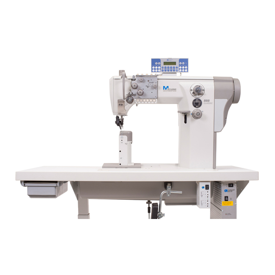
Product description The Dürkopp Adler 888 is a special sewing machine for universal use. • It is a double lockstitch post bed sewing machine . • It has a two step feed. A lower wheel feeder and a driven roller presser feed in two steps, a needle feed feeds in the first step only. -
Page 8: Subclasses
Subclasses 888-160020 Single-needle double lockstitch post bed sewing machine with feed wheel, needle feed with driven roller foot and large hook. - Page 9 888-356152 Single-needle double lockstitch post bed sewing machine with feed wheel, needle feed with driven roller foot and regular hook, electro-magnetic thread cutter, electro-magnetic seam bartacking and sewing foot lifting, equipped with electro motor driven edge trimmer. Short stitch equipment: By pressing a key on the machine head a complete stitch with shortened stitch length is sewn.
-
Page 10: Optional Equipment
Optional equipment The following optional equipments are available for the class 888 : Order No. Optional equipment Subclasses 9880 888101 Integrated sewing light with 2 LED, incl. x x x x x x x x x x x dimmer transformer... -
Page 11: Technical Data
Technical data Noise: Workplace-related emission value in accordance with DIN 45635-48-A-1-KL2 888-160020 LC = _dB (A) Stitch length: _ mm Sewing foot stroke: mm Speed: ____ min Material: 888-160122 LC = _dB (A) Stitch length: _ mm Sewing foot stroke: mm Speed: ____ min... - Page 12 Technical data of the subclasses Subclasses Type of stitch Lock stitch 301 Hook type Number of needles Needle system Needle size (depending on E-No.) [Nm] Max. thread thickness [Nm] 10/3 Stitch length [mm] Forwards Backwards Max. Speed [min 3000 Number of stitches with factory setting [min 2500...
-
Page 13: Operation
Operation Threading the needle thread Caution! Risk of injury! Turn off the main switch. The needle thread may only be threaded with the sewing machine switched off. – Thread the single needle machine according to fig. (A). If the machine is equipped for heavy sewing, wind the thread around the pin (1). -
Page 14: Winding The Hook Thread
Winding the hook thread – Thread the thread according to the picture. – Insert the thread under the knife (1) and tear off by pulling in the arrow direction (2). – Fix the bobbin and press the lever (3) in the direction (4). –... -
Page 15: Adjusting The Thread Tension
Adjusting the thread tension 6.4.1 Adjusting the hook thread tension Caution! Risk of injury! Turn off the main switch. The hook thread tension may only be adjusted with the machine switched off. – Adjust the hook thread tension via the screw (1). Insert a screwdriver through the hole (2). -
Page 16: Adjusting The Needle Thread Tension
6.4.2 Adjusting the needle thread tension Adjusting the pre-tensioner (1) – Adjust the supplementary tensioner (1) so that it has the lowest tension possible, but so high that, when taking out the sewn material after the preceding trimming (when the tensioners (2) and (3) are switched off), the thread is not pulled out of the tensioner (1). - Page 17 Adjusting tensioners (2) and (3) CLASSIC machines with pneumatic control – Through pressing the key (5) the additional tension (2) will be switched off. If the key (5) is pressed anew, the additional tension will be activated again. The connectable additional tension (2) helps in quick adjustment of the needle thread tension, for example in order to get a tight stitch formation with regular seams when sewing different materials.
-
Page 18: Switching On/Off The Thread Tensioners
Switching on/off the thread tensioners ECO and CLASSIC machines with electro-magnetic control – When pulling the hand lever (1) towards the operator, the tensioners (3) and (4) are switched off. – Tensioner (2) is never switched off. Manually controlled machines (without thread trimming) –... -
Page 19: Function Of The Thread Main Tension And The Thread Supplementary Tension In Relation To The Sewing Foot Lifting
6.5.1 Function of the thread main tension and the thread supplementary tension in relation to the sewing foot lifting The thread supplementary tension can, at any time, be switched on or off by actuating key 4 (see chapter 6.5) of the key pad. To this end, the parameter F-147 must be set on “1". -
Page 20: Adjusting The Thread Regulator
Adjusting the thread regulator 1 2 3 4 The thread regulator (2) controls the quantity of needle thread required for stitch formation. The thread regulator must be precisely adjusted for an optimum result. – Loosen the screw (1), shift the thread regulator (2), and tighten the screw (1). -
Page 21: Changing The Needle With Single-Needle Machines With The Hook On The Right
Changing the needle with single-needle machines with the hook on the right Caution! Risk of injury! Replace the needle with the main switch switched off and the motor stopped. – Draw the lever (1) in your direction to loosen the screw fixing the needle. -
Page 22: Changing The Needle With Single-Needle Machines With The Hook On The Left (Machine With Lower Thread Trimmer)
Changing the needle with single-needle machines with the hook on the left (machine with lower material trimming) Caution! Risk of injury! Turn off the main switch. The needle may only be changed with the sewing machine switched off – Draw the lever (1) in your direction to loosen the screw fixing the needle. -
Page 23: Changing The Needle With Double-Needle Machines
Changing the needle with double-needle machines Caution! Risk of injury! Turn off the main switch. The needles may only be changed with the sewing machine switched off. – Loosen the screws (1). – Remove the needle and insert new ones with the needle scarf (2) oriented as shown above [see section (3) or (4)]. -
Page 24: Lifting And Folding The Roller Presser
6.10 Lifting and folding the roller presser Lifting the roller presser with a hand lever – Lift the roller presser by the lever turning (1) in the arrow direction to the stop (the roller presser remains lifted, the lever (1) remains tilted). -
Page 25: Sewing-Foot Pressure
Roller presser folding Caution! Risk of injury! Roller presser folding to be done at main switch off and standing motor. – Lift the roller presser with the hand lever. – Lift the roller presser by pressing in the signed direction. 6.11 Sewing-foot pressure 6.11.1 Setting through the setting wheel –... -
Page 26: Constant Sewing-Foot Pressure Through The Cylinder
6.11.2 Constant sewing-foot pressure through the cylinder – The pressure of the roller presser will be set via the setting wheel (2). – Pull the handle (2) downwards and turn it until the desired operating pressure is shown on the manometer (1). 6.12 Sewing backward (backtacking) Backtacking with the lever –... -
Page 27: Setting The Stitch Length
(3). CLASSIC machines with pneumatic control The special sewing machine 888 is equipped with two setting wheels. Thus, two different stitch lengths can be sewn, that are activated by actuating a key during the sewing process. -
Page 28: Switching On The Safety Clutch At The Hook Blocking
6.14 Switching on the safety clutch at the hook blocking – If the thread gets in the hook way, the hook gets blocked and it is subsequently disconnected from the motor by the safety clutch. Caution! Risk of injury! Turn off the main switch. Switch the safety clutch on, with the sewing machine switched off. -
Page 29: Starting The Manually Controlled Machine With The Clutch Motor
6.15 Starting up the manually controlled machine with a clutch motor – Switch on the motor (1) using the switch (2). – Tread the pedal (3). The motor friction clutch is activated and the sewing machine starts running. – The sewing speed is determined through the pedal (3). –... -
Page 30: Using The Pedal
6.16 Controlling the machine equipped with a positioning motor 6.16.1 Using the pedal The pedal position is scanned by a sensor distinguishing 16 levels. The meaning is given in the table: Pedal position Pedal motion Meaning Over heel fully backwards Command for thread trimming (seam finishing) Over heel slightly backwards Command for foot lifting... -
Page 31: Using The Key
6.16.2 Using the key 10 9 Function Manual sewing backward The machine sews backward stitches as long as the key is being pushed. Needle positioning to the upper or lower position By parameter F-242 (DA321) the following key functions can be defined: 1 = needle up/down 2 = needle up 3 = one stitch... - Page 32 Function 8 and 9 Display for empty bobbin with machines equipped with residual thread monitor (left/right bobbin). LED display “power on” Example of Through the arresting of the pin 11 under the key 1 it is possible to transfer the key 1 function arresting pins: to key 7:...
-
Page 33: Material Edge Trimmer Control
6.17 Sewn material edge trimmer control 6.17.1 Switching on/off edge trimmer Switch on – Push the knob (1) in the arrow (A) direction, or pull the handle (2) in the arrow (B) direction until the trimming knife gets from the initial position (3) to the switch on position (4). -
Page 34: Switching On/Off Material Guide
6.17.2 Switching on/off material guide Switch on – Put the guide (1) in a working position by pushing the lever (2) upwards or by pulling the guide body (3) downwards. Switch off – Shift the ball (4) upwards and to the left. The guide element (5) lifts in a setting position. -
Page 35: Material Guide Adjustment
6.17.3 Material guide adjustment – Adjust the guide element (1) height with a bolt (2). The guide element is lifted, when tightening the bolt, and vice versa. If the bolt (2) strikes the end of the adjustment range, the latter can be widened by the bolt (3), loosening the plate (4) shifting to a different position and its repeated fixing. -
Page 36: Disengaging The Needle Bar With Subclass 888-460522
6.17.4 Disengaging the needle bar with subclass 888-460522 The needle bars are switched on and off with the “L” and “R” keys. – Press the “L” key. The key is illuminated. The left needle bar is switched off. – Sewing. -
Page 37: Positioning Drive Efka Dc1550/Da321G
Positioning drive Efka DC1550/DA321G DA321G control contains all necessary operating elements to switch the functions over and to set the parameters. The operation is possible without the control panel, it is not possible only to program the sewing. It is possible to connect the control panel V810 and V820, which are available as an attachment. -
Page 38: Machine Automatic Function
Sewing with machine with positioning motor Machine automatic functions The machine has the below functions which are automatically performed during the seam sewing depending on: – Pre-selection – Pedal position (according to the machine operator´ s selection) – Working phase of seam sewing Automatic function Pre-selection Needle positioning... -
Page 39: Example Of Machine Operation At Sewing
Automatic function codes are described in the attached drive manufacturer´ s Instruction Leaflet. The drive manufacturer’s Instruction Leaflet for Efka DA321G drive is available on website www.efka.net. Some automatic functions can be preset by means of push buttons. Their description is included in the booklet “Efka Operation Instructions”. -
Page 40: Maintenance
Maintenance Cleaning and checking Caution! Risk of injury! Turn off the main switch. Maintenance may only be carried out with the machine switched off! Maintenance work must be carried out no less frequently than at the intervals given in the tables (see ”operating hours” column). Maintenance intervals may need to be shorter when processing heavy-shedding materials. - Page 41 Maintenance work Explanation Operating to be carried out hours - Clean the oil sump Clean the oil sump (1) of dirt and contaminated oil. (you may use a special vacuum cleaner.) - Clean fan grille Remove lint and pieces of thread from air-intake openings (2) and (3) (e.g.
- Page 42 Maintenance work Explanation Operating to be carried out hours Pneumatic system The water level must not rise to the level of - Check water level in the filter cartridge (1). pressure regulator. - After unscrewing the drain screw (3), the water under pressure will flow out of the water separator (2).
-
Page 43: Lubrication
11.2 Lubrication Caution! Risk of injury! Oil can cause skin eruptions. Avoid protracted contact with the skin. In the event of contact, thoroughly wash the affected area. Caution! The handling and disposal of mineral oils is subject to legal regulation. Deliver used oil to an authorised collection point. - Page 44 Notes:...
- Page 45 6.1.3 Values of parameters specific for this class 888 ......Setting of machine positioning ........
- Page 46 Contents Page: Sewing test ..........
-
Page 47: Scope Of Delivery
Scope of delivery The purchaser can order a complete machine, or some components only. Prior to setting up, please check that all the required parts are present. This description refers to a special sewing machine, of which all individual components can completely be delivered by Dürkopp Adler AG. -
Page 48: Transport Packing Of Assembled Machine
Transport packing of assembled machine If the machine is supplied in assembled condition, the following transport packing must be removed: – Safety straps and wooden battens on the machine head and stand. – Safety blocks and straps on the sewing drive. Assembling the stand Assembling the stand components –... -
Page 49: Assembling The Table Top
Assembling the table top 3.2.1 Assembling the table top in the machine with the motor on the table top – Turn the table top (1) upside down. – Screw the drawer (2). – Put the oil sump (3) on the recess in the table top and slide it in the arrow direction (4) till the relevant protrusions of the oil sump are seated on the recess contour. -
Page 50: Assembling The Table Top With The Motor On The Machine Head (Direct Drive)
3.2.2 Assembling the table top with the motor on the machine head (direct drive) – Turn the table top (1) upside down. – Screw the electric cable channel (2). – Screw the pedal position sensor (3). – Screw the electric cable clip (4). –... -
Page 51: Mounting The Pressure Regulator For The Sewing Foot To The Table Top
3.2.3 Mounting the pressure regulator for the sewing foot to the table top – Put the pressure regulator (1) in the holder (9) and secure it using the nut (10). – Mount the components of the pneumatic circuit to the table top as shown in the illustration below. - Page 52 Connect the components of the pneumatic circuit according to the drawing below.
-
Page 53: Setting The Working Height
Setting the working height – The stand height is adjustable between 750 and 900 mm. – Loosen the screws (1). – Set the required table top height and make sure that it is identical on both sides. To do that, use the scale on the stand feet. Set the stand height so that it corresponds with the operator’s body proportions. -
Page 54: Assembling The Machine Head
Assembling the machine head Fitting the machine head – If the sewing machine is equipped with a motor on the table top, insert the machine head (1) vertically in the recess in the table top. – If the sewing machine is equipped with a motor (drive) on the machine head, tilt the machine head (2) and insert it in the table top recess. -
Page 55: Fitting The Machine Head Drive With A V-Belt
Fitting the machine head drive with a V-belt This paragraph applies only to the machines with the motor on the table top. – Mount the V-belt pulley (1) and the V-belt (2). Both items are included in the set of parts. –... -
Page 56: Fitting The Belt Guards
Fitting the belt guards – Disassembly the hand wheel (1). – In the machines with the motor on the table top mount the guard (2) on the machine head (the guard is included in of the motor part set) and mount the guard (3) on the motor (the guard is included in the motor package). -
Page 57: Adjustment Of Pedal Position
Adjustment of pedal position – Adjust the side position of the pedal (1) so that its center lies on the needle axis. – Adjust the draw rod (2) so that the foot axis is perpendicular to the pedal surface. Caution! Risk of injury! Failure to keep the determined pedal position can cause damage to the operator’s locomotion system. -
Page 58: Fitting The Knee Lever And Oil Pump Pipe
Fitting the knee lever and oil pump pipe – Lift the sewing foot with the hand lever. – Tilt the machine head (1). – Slide the shaft (3) in the lever (4). – Screw the screw (5) with the washer (6) in the shaft (3). –... -
Page 59: Fitting The Proximity Switch
Fitting the proximity switch – The proximity switch (1) is mounted to certain positioning motors (drives) only. In that case it is part of the drive supply. – Slide the proximity switch (1) in the arrow (2) direction on the hand wheel shaft so that the carrier pin (3) fits in the proximity switch groove. -
Page 60: Fitting The Connecting Cable, Control Panel And Sewing Diode Lamp On The Machine Head
Fitting the connecting cable, control panel and sewing diode lamp on the machine head – The connecting cable (1) is supplied with every machine with the positioning motor (drive). – The control panel (2) had to be ordered separately (optional equipment). -
Page 61: Electrical Connection
Electrical connection The machine drive is supplied from the low voltage network. Caution! All work on the electrical equipment of this special sewing machine may only be carried out by qualified electricians or other appropriately trained persons. Remove the mains plug before carrying out any work! Electrical connection to low voltage network According to the selected type the machine drive has a one-phase or three-phase supply. - Page 62 5.1.1 Sewing lamp transformer connection to network voltage Caution! Risk of electric current injury! The sewing lamp transformer is not switched off by the main switch (EN 60 204-31)! At the sewing lamp installation and repair inside the transformer box, e.g. at a fuse replacement, the mains plug must be disconnected from the power outlet.
-
Page 63: Grounding
Grounding – The grounding conductor (1) is included in the accessory package of the machine head. – Connect the conductor (1) to the plug (2) and pull its opposite end under the table top. – Screw the opposite end of the grounding conductor to the relevant grounding point of the drive (indicated –... -
Page 64: Connection Of Head To Efka Dc1550/Da321G Drive
Connection of the head to Efka DC1550/DA321G drive Efka DC1550/DA321G direct drive is fixed directly on the machine head. The motor synchronizer is incorporated in the motor body and it is not located on the hand wheel (this applies, however, only for the 1:1 gear reduction motor –... -
Page 65: Mounting The M-Control Pcb
Mounting the M-Control PCB – Mount the M-Control PCB 1 to the right of the set value initiator 2. – Connect the compressed air hose 4 to the compressed air maintenance unit 8. – Fix the two compressed air hoses 7 from the machine head onto the throttle valves / solenoid valves 5 and 6. -
Page 66: Setting The Switch On The M-Control Pcb
Setting the switch on the M-Control PCB With machines having a disconnectable needle bar the switch 1 on the M-Control PCB has to be in position “2". -
Page 67: Adjustment Of Efka Positioning Motor (Drive)
6.1.2 Setting of Efka drive parameters specific for class 888 Caution! Change of the parameter value must be performed with consideration and in a responsible way. A false setting of the control may cause the... -
Page 68: Values Of Parameters Specific For This Class 888
6.1.3 Values of parameters specific for this class 888 Parameter change for machines with gear rate of 28/28 teeth Parameter Original value New value Parameter description 290* Class of the machine Max. sewing speed Reference position (see chapter 6.2.2) Parameter change for machines with gear rate 18/28 teeth... -
Page 69: Checking Of Set Positions
6.2.3 Checking of set positions Position 1 – Switch on the network switch. – Tread the pedal forwards shortly and release. The machine is stopped in the position 1 (see chapter 6.2.1). – Check the angle on the hand wheel scale (225° ± 5°). Position 2 –... -
Page 70: Pneumatic Connection
Pneumatic connection CLASSIC machines with pneumatics. Attention! The special sewing machine’s operating pressure is 6 bar. – Mount the maintenance unit 1 to the stand brace as shown in the illustration. – Screw in the elbow fitting 2 (in the accessories) and connect the hose 3 from the machine head to the elbow fitting 2. -
Page 71: Lubrication
Lubrication Before start, the machine must be lubricated properly with oil according to chapter 9.2 in the operating instructions. Sewing test This test can be carried out only after the machine is set completely. – Thread in the bobbin-winder thread. (see operating instructions). –... - Page 72 Notes:...
- Page 73 Änderung der technischen Dokumentation Modification of the technical documentation Modification de la documentation tecnique Modificación de la documentación técnica Modificazione della documentazione tecnica Die vorliegende Anleitung hat sich nach Drucklegung geändert. Bitte tauschen Sie die beiliegenden Seiten in Ihrer Landessprache aus. The present instructions have changed since their last print out.
- Page 75 Additional Instructions Machines with Integrated Motor...
-
Page 76: About This Manual
About this manual 1 About this manual These additional instructions are supplementary to the manual of class 888 machines. They describe operation and functioning measures of machines with integrated motor that differ from ma- chines without integrated motor. The additional instructions do not constitute a self-contained doc- ument, but are only valid in combination with the respective in- struction manual. - Page 77 ECO-machines 3 ECO-machines 3.1 Operation Fig. 1: Switching ECO-machines on and off (1) - LEDs indicating the status (2) - Main switch for the power supply ECO-machines with integrated motor are switched on and off via the main switch (5) on the machine post. Switching the machine on 1.
- Page 78 ECO-machines Fig. 2: Operator settings with ECO-machines (1) - Potentiometer P1 to decrease the speed (2) - Button S1 for the needle's stopping position (3) - Button S2 for the softstart Setting the maximum speed 1. Turn the potentiometer P1 (1). •...
- Page 79 CLASSIC-machines CLASSIC-machines . Operation Fig. 3: Switching CLASSIC-machines on and off Operating panel on the Control beneath the table machine post (1) - LEDs indicating the status (2) - Button for the sewing light (3) - Main switch for power supply (4) - Control light CLASSIC-machines are switched on and off at the control under- neath the table top (...
- Page 80 CLASSIC-machines Fig. 4: Switching the sewing light on and setting the light intensity (1) - Potentiometer P1 for an infinitely variable setting of intensity (2) - Button S1 for the single-diode sewing light (3) - Button S2 for the integrated sewing light Switching the sewing lights on and off 1.
- Page 81 CLASSIC-machines 4.2 Sewing light connection DANGER Risk of death due to electric shock The sewing light control is directly connected to the mains supply and is live even when the main switch is switched off. Therefore it is essential to pull out the mains plug, before you connect the sewing light.
- Page 82 DÜRKOPP ADLER AG Potsdamer Str. 190 33719 Bielefeld Germany Phone +49 (0) 521 925 00 E-Mail: service@duerkopp-adler.com www.duerkopp-adler.com...
Need help?
Do you have a question about the 888 and is the answer not in the manual?
Questions and answers