Table of Contents
Advertisement
TopPage
SENSOR
CHAPTER 1. BEFORE SERVICING
CHAPTER 2. WARNING TO SERVICE PERSONNEL
CHAPTER 3. PRODUCT SPECIFICATIONS
CHAPTER 4. APPEARANCE VIEW
CHAPTER 5. OPERATION SEQUENCE
CHAPTER 6. FUNCTION OF IMPORTANT COMPO-
NENTS
CHAPTER 7. TROUBLESHOOTING GUIDE
CHAPTER 8. TEST PROCEDURES
Parts marked with "
" are important for maintaining the safety of the set. Be sure to replace these parts with specified ones for maintaining the
safety and performance of the set.
SERVICE MANUAL
1200 WATTS
CONVENIENT MENUS
EXPRESS
EASY
DEFROST
DEFROST
MELT
SENSOR
MODELS
REHEAT
SOFTEN
SENSOR COOK
FRESH
FROZEN
VEGETABLES
VEGETABLES
RICE
JACKET
POTATO
PASTA
QUICK
EASY
MEALS
MEALS
LESS
MORE
POWER
INFO
LEVEL
TIMER
In the interest of user-safety the oven should be restored to its
original condition and only parts identical to those specified
should be used.
CONTENTS
CHAPTER 9. CHECK IN THE EVENT OF NO MICRO-
WAVE COOKING
CHAPTER 10. SERVICING FOR TOUCH CONTROL
PANEL
CHAPTER 11. PRECAUTIONS FOR USING LEAD-
FREE SOLDER
CHAPTER 12. COMPONENT REPLACEMENT AND
ADJUSTMENT PROCEDURE
CHAPTER 13. MICROWAVE MEASUREMENT
CHAPTER 14. CIRCUIT DIAGRAMS
Parts Guide
S0119R350YPJS
MICROWAVE OVEN
R-350Y(S)
R-350Y(W)
This document has been published to be used for
after sales service only.
The contents are subject to change without notice.
R-350Y(S)
Advertisement
Table of Contents

Subscribe to Our Youtube Channel
Related Manuals for Sharp R-350Y


Summary of Contents for Sharp R-350Y
-
Page 1: Microwave Oven
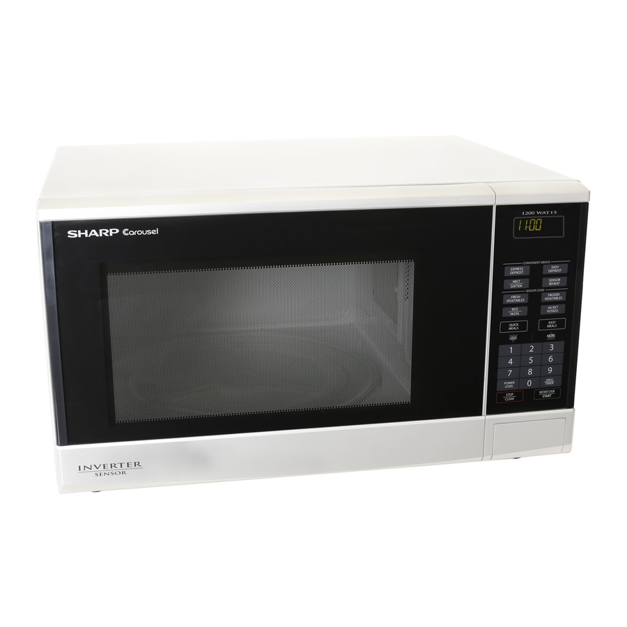
TopPage R-350Y(S) SERVICE MANUAL S0119R350YPJS MICROWAVE OVEN 1200 WATTS R-350Y(S) CONVENIENT MENUS EXPRESS EASY DEFROST DEFROST MELT SENSOR MODELS REHEAT SOFTEN SENSOR COOK FRESH FROZEN VEGETABLES VEGETABLES RICE JACKET POTATO PASTA QUICK EASY R-350Y(W) MEALS MEALS LESS MORE POWER INFO... -
Page 2: Table Of Contents
CONTENTS CHAPTER 1. BEFORE SERVICING CHAPTER 9. CHECK IN THE EVENT OF NO MI- GENERAL IMPORTANT INFORMA- CROWAVE COOKING TION ............1-1 CAUTION MICROWAVE RADIATION ..1-1 CHAPTER 10. SERVICING FOR TOUCH CON- WARNING........... 1-1 TROL PANEL SERVICING FOR TOUCH CONTROL CHAPTER 2. -
Page 3: Chapter 1. Before Servicing
R-350Y(S) CHAPTER 1. BEFORE SERVICING [1] GENERAL IMPORTANT INFORMATION This Manual has been prepared to provide Sharp Corp. Service engineers with Operation and Service Information. It is recommended that service engineers carefully study the entire text of this manual, so they will be qualified to render satisfactory customer ser- vice. -
Page 4: Chapter 2. Warning To Service Personnel
R-350Y(S) CHAPTER 2. WARNING TO SERVICE PERSONNEL The ovens contain circuitry capable of producing very high voltage and current, contact with following parts may result in a severe, possibly fatal, electrical shock. (Example) Inverter unit, Magnetron, High Voltage Harness etc.. -
Page 5: When The Testing Is Completed
R-350Y(S) [2] When the testing is completed, 1. CARRY OUT 3D CHECKS. 2. CARRY OUT 4R CHECKS. 2-1.Reconnect all leads removed from components during testing. 2-2.Reinstall the outer case. 2-3.Reconnect the power supply cord after the outer case is installed. -
Page 6: Chapter 3. Product Specifications
R-350Y(S) CHAPTER 3. PRODUCT SPECIFICATIONS 230 - 240 Volts Power Requirements 50 Hertz Single phase, 3 wire earthed Power Consumption Initial : 1.90kW 8.0A Steady : 1.15kW 5.0A 1200 watts nominal of RF microwave energy (IEC Test Procedure) Power Output... -
Page 7: Chapter 4. Appearance View Oven
R-350Y(S) CHAPTER 4. APPEARANCE VIEW [1] OVEN 1. Door open button 9. Touch control panel 2. Oven lamp 10.Liquid crystal display 3. Door hinges 11. Ventilation openings 4. Door safety latches 12.Power supply cord 5. See through door 13.Turntable 6. Door seal and sealing surfaces 14.Roller stay... -
Page 8: Chapter 5. Operation Sequence 1] Off Condition
R-350Y(S) CHAPTER 5. OPERATION SEQUENCE 1) When the oven door is opened during or after the cycle of a [1] OFF CONDITION cooking program, the 1st. latch switch and 2nd. interlock relay Closing the door activates all door interlock switches (1st. latch switch control switch must open their contacts first. -
Page 9: Power Output Reduction
R-350Y(S) 1. Cooking Sequence. 1. 1.Operate the oven in sensor cooking mode by referring to the operation manual. NOTE: The oven should not be operated on SENSOR immediately after plugging in the unit. Wait two minutes before cooking on SENSOR. -
Page 10: Chapter 6. Function Of Important Com
R-350Y(S) CHAPTER 6. FUNCTION OF IMPORTANT COMPONENTS [1] DOOR OPEN MECHANISM [6] OVEN TEMPERATURE FUSE The door is opened by pushing the open button on the control panel, The temperature fuse, located on the top of the oven cavity, is refer to the Figure D-1. -
Page 11: Chapter 7. Troubleshooting Guide
R-350Y(S) CHAPTER 7. TROUBLESHOOTING GUIDE When troubleshooting the microwave oven, it is helpful to follow the IMPORTANT: Sequence of Operation in performing the checks. Many of the possible If the oven becomes inoperative because of a blown fuse F10A in the causes of trouble will require that a specific test be performed. -
Page 12: Watts
R-350Y(S) CHAPTER 8. TEST PROCEDURES [1] A: MAGNETRON (MG) TEST NEVER TOUCH ANY PART IN THE CIRCUIT WITH YOUR HAND OR AN INSULATED TOOL WHILE THE OVEN IS IN OPERATION. CARRY OUT 3D CHECKS. Isolate the magnetron from the high voltage circuit by removing all leads connected to the filament terminal. -
Page 13: B: Switch Test
R-350Y(S) CAUTION: 1 C CORRESPONDS TO 120 WATTS. REPEAT MEASUREMENT IF THE POWER IS INSUFFICIENT. 1000g 1000g 1000g T1 C T2 C Heat up for 38 sec. [2] B: SWITCH TEST CARRY OUT 3D CHECKS. Isolate the switch to be tested and using an ohmmeter check between the terminals as described in the following table. -
Page 14: F: Noise Filter Test
R-350Y(S) [6] F: NOISE FILTER TEST CARRY OUT 3D CHECKS. Disconnect the leads from the terminals of the noise filter. Using an ohmmeter, FUSE F10A check between the terminals as described in the following table. LINE CROSS CAPACITOR 2.2μF /AC250V... -
Page 15: H: Key Unit (Membrane Switch) Test
R-350Y(S) [8] H: KEY UNIT (MEMBRANE SWITCH) TEST 1. CARRY OUT 3D CHECKS. 2. If the display fails to clear when the STOP/CLEAR pad is depressed, first verify the flat ribbon cable is making good contact, verify that the 2nd. - Page 16 R-350Y(S) 6) The Sensor works with food at normal storage temperature. For example, chicken pieces would be at refrigerator temperature and canned soup at room temperature. 7) Avoid using aerosol sprays or cleaning solvents near the oven while using Sensor settings. The sensor will detect the vapor given of by the spray and turn off before food is properly cooked.
- Page 17 R-350Y(S) If the above is not the case, the control unit is probably defective. If the above is proper, the humidity sensor is probably defective. 10) Disconnect the power supply cord, and then remove outer case. 11) Open the door and block it open.
-
Page 18: Chapter 9. Check In The Event Of No Microwave Cooking
R-350Y(S) CHAPTER 9. CHECK IN THE EVENT OF NO MICROWAVE COOKING Check of high voltage sections is very dangerous. Therefore, after the inverter boards (M and AC3) and 230 - 240V at the primary terminal are con- firmed to be satisfactory, disconnect the main power and wait for at least one (1) minute before starting the check. - Page 19 R-350Y(S) Adjustment of microwave power The microwave power (100% power level) can be adjusted as follows. At step 10, adjust the power so that the "3A" should be indicated at "YY" in the display for this model. Step Operation Display...
-
Page 20: Chapter 10. Servicing For Touch Con
R-350Y(S) CHAPTER 10. SERVICING FOR TOUCH CONTROL PANEL [1] SERVICING FOR TOUCH CONTROL PANEL b) On some models, the power supply cord between the touch 1. Precautions for Handling Electronic Components control panel and the oven proper is long enough that they may This unit uses CMOS LSI in the integral part of the circuits.When han-... -
Page 21: Chapter 11. Precautions For Using Lead-Free Solder
R-350Y(S) CHAPTER 11. PRECAUTIONS FOR USING LEAD-FREE SOLDER 1. Employing lead-free solder The "Main PWB" of this model employs lead-free solder. This is indicated by the "LF" symbol printed on the PWB and in the service manual. The suf- fix letter indicates the alloy type of the solder. -
Page 22: And Adjustment Procedure 1] Before Operating
R-350Y(S) CHAPTER 12. COMPONENT REPLACEMENT AND ADJUSTMENT PROCE- DURE [1] BEFORE OPERATING WARNING AGAINST HIGH VOLTAGE: Microwave ovens contain circuitry capable of producing very high voltage and current, contact with following parts may result in severe, possibly fatal, electric shock. -
Page 23: Inverter Unit Replacement
R-350Y(S) WARNING: RISK OF ELECTRIC SHOCK. DISCHARGE THE HIGH- NOTE: Step 1, 2 and 6 form the basis of the 3D checks. VOLTAGE CAPACITORS BEFORE SERVICING. CAUTION: DISCHARGE HIGH VOLTAGE CAPACITOR BEFORE 8. Do not operate the oven with the outer case removed. -
Page 24: Positive Lock Connector (No-Case Type) Removal
R-350Y(S) [5] POSITIVE LOCK CONNECTOR (NO-CASE TYPE) REMOVAL 1. CARRY OUT 3D CHECKS. Terminal 2. Push the lever of positive lock connector. 3. Pull down on the positive lock connector. Positive lock connector CAUTION: WHEN CONNECTING THE POSITIVE LOCK CONNEC-... -
Page 25: Cooling Fan Motor Removal
R-350Y(S) [9] COOLING FAN MOTOR REMOVAL 7. Connect the wire leads to the fan motor, referring to the pictorial 1. REMOVAL diagram. 1. CARRY OUT 3D CHECKS. 2. Disconnect the wire leads from the fan motor. 3. INFORMATION (How to remove the fan blade) 3. -
Page 26: 1St. Latch Switch, 2Nd. Interlock Relay Control Switch And Monitor Switch Removal
R-350Y(S) 2. REINSTALL 1. Insert the moulding cord stopper of power supply cord into the square hole of the rear cabinet, referring to the Figure C-3 (b). Power Supply Cord 2. Install the earth wire lead of power supply cord to the oven cavity Moulding back plate with one (1) screw and tight the screw. -
Page 27: Door Replacement
R-350Y(S) [13] DOOR REPLACEMENT 1) Make sure that 1st. latch switch, 2nd. interlock relay control switch 1. REMOVAL and monitor switch are operating properly. (Refer to chapter “Test 1. Disconnect the power supply cord. Procedures”.). 2. Open the door slightly. -
Page 28: Chapter 13. Microwave Measurement
R-350Y(S) CHAPTER 13. MICROWAVE MEASUREMENT After adjustment of door latch switches, monitor switch and door are completed individually or collectively, the following leakage test must be per- formed with a survey instrument and it must be confirmed that the result meets the requirements of the performance standard for microwave oven. -
Page 29: Oven Schematic
R-350Y(S) CHAPTER 14. CIRCUIT DIAGRAMS [1] Oven Schematic SCHEMATIC NOTE: CONDITION OF OVEN 1. DOOR CLOSED. 2. CLOCK APPEARS ON DISPLAY. NOISE FILTER UNIT OVEN TEMP FUSE FUSE F10A RY-1 RY-2 RY-3 HUMIDITY SENSOR CONTROL INVERTER UNIT UNIT 2ND. INTERLOCK... -
Page 30: Pictorial Diagram (Figure S-1)
R-350Y(S) [2] Pictorial Diagram (Figure S-1) CN-A Figure S-1. Pictorial Diagram 14 – 2... -
Page 31: Control Unit Circuit (Figure S-2)
R-350Y(S) [3] Control Unit Circuit (Figure S-2) PCOM0 PCOM1 PCOM2 PCOM3 (R80) 0.1uF/50V C100 0.1uF/50V C101 (J7) (J8) (C64) 37.4KF R102 75KF R101 150KF R100 300KF 620K 360KF (R78) UDZ4.3B 4.7K ZD10 0.1uF/ R103 R104 0.1uF/50V 3.3K 3.32KD (C94) 47uF/16V... -
Page 32: Printed Wiring Board (Figure S-3)
R-350Y(S) [4] Printed Wiring Board (Figure S-3) Figure S-3. Printed Wiring Board of Power Unit 14 – 4... -
Page 33: Inverter Unit Circuit (Figure S-4)
R-350Y(S) [5] Inverter Unit Circuit (Figure S-4) 9.4V Figure S-4. Inverter unit circuit 14 – 5... - Page 34 R-350Y(S) 14 – 6...
-
Page 35: Parts List
FPADBA542WRKZ INTO THE SPAKHA012WREZ OVEN CAVITY TRAY PAD ASSY Not replaceable items. (CPADBA317WRKZ) PACKING CASE SPAKCF221WREZ [R-350Y(S)] SPAKCF223WREZ [R-350Y(W)] This document has been published to be used for after sales service only. The contents are subject to change without notice. - Page 36 R-350Y(S) [1] OVEN PARTS 7-10 7-10 7-10 1-13 1-12 4-15 4-12 4-23 1-15 4-16 7-11 4-24 7-10 4-25 7-10 4-19 4-14 1-11 4-17 7-10 4-10 4-18 4-12 4-11 7-10 4-12 7-10...
-
Page 37: Oven Parts
Magnetron 1-12 FPWBFA461WRKZ Noise filter unit 1-13 QFS-CA026WRZZ Fuse f10a 1-15 FDTCTA230WRKZ Humidity sensor CABINET PARTS GCABUA935WRPZ Outer case cabinet [R-350Y(S)] GCABUA883WRPZ Outer case cabinet [R-350Y(W)] GDAI-A489WRWZ Bottom plate GLEGPA074WRE0 OVEN PARTS PHOK-A131WRFZ Latch hook LANGQA841WRPZ Inverter angle NFANJA053WRFZ Fan blade... - Page 38 R-350Y(S) [2] DOOR AND CONTROL PANEL PARTS 5-11 5-10 1-14 Actual wire harness may be different from illustration. 1-10...
-
Page 39: Control Panel Parts
FW-VZC336WREZ Main wire harness CONTROL PANEL PARTS DPWB-B044DRKZ Control unit PSHEPB587WREZ Graphic sheet QSW-KA061DRZZ Membrane switch JBTN-B631WRTZ Open button R-350Y(S) JBTN-B630WRFZ Open button R-350Y(W) MSPRCA050WRE0 Button spring XEPS730P08XS0 Screw : 3mm x 8mm HPNLCC346WRTZ Control panel R-350Y(S) HPNLCC345WRFZ Control panel R-350Y(W) - Page 40 EndPage...
Need help?
Do you have a question about the R-350Y and is the answer not in the manual?
Questions and answers
What year was it sold in Australia
The Sharp R-350Y was sold in Australia in 2011.
This answer is automatically generated