Table of Contents
Advertisement
CAUTION, MICROWAVE RADIATION ............................................................................................................. 1
WARNING .......................................................................................................................................................... 1
PRODUCT SPECIFICATIONS ......................................................................................................................... 2
GENERAL INFORMATION ................................................................................................................................ 2
APPEARANCE VIEW ....................................................................................................................................... 3
OPERATION SEQUENCE ................................................................................................................................ 4
FUNCTION OF IMPORTANT COMPONENTS ................................................................................................ 5
SERVICING AND TROUBLESHOOTING GUIDE ............................................................................................ 6
TEST PROCEDURE ......................................................................................................................................... 8
TOUCH CONTROL PANEL ............................................................................................................................. 13
COMPONENT REPLACEMENT AND ADJUSTMENT PROCEDURE ........................................................... 18
MICROWAVE MEASUREMENT .................................................................................................................... 23
WIRING DIAGRAM ......................................................................................................................................... 24
PICTORIAL DIAGRAM ................................................................................................................................... 25
POWER UNIT CIRCUIT .................................................................................................................................. 26
CPU UNIT CIRCUIT ........................................................................................................................................ 27
PRINTED WIRING BOARD ............................................................................................................................. 28
PARTS LIST ................................................................................................................................................... 29
SERVICE MANUAL
EXPRESS MENUS
EXPRESS
EXPRESS
EXPRESS
DEFROST
COOK
MEAL
INFORMATION COOK
EASY
RICE/
VEGETABLES
DEFROST
PASTA
HEALTHY MENU
LOW FAT
VEGETARIAN
MEALS
MEALS
MODEL
CONVENIENCE
REHEAT
MEALS
MENU
LESS
MORE
HELP
POWER
TIMER
LEVEL
CLOCK
STOP
INSTANT COOK
CLEAR
START
In interests of user-safety the oven should be restored to its
original condition and only parts identical to those specified
should be used.
TABLE OF CONTENTS
SHARP CORPORATION
MICROWAVE OVEN
R-350J
R-350J
S8404R350JPJ/
Page
Advertisement
Table of Contents

Related Manuals for Sharp R-350J


Summary of Contents for Sharp R-350J
-
Page 1: Table Of Contents
R-350J SERVICE MANUAL S8404R350JPJ/ MICROWAVE OVEN EXPRESS MENUS EXPRESS EXPRESS EXPRESS DEFROST COOK MEAL INFORMATION COOK EASY RICE/ VEGETABLES R-350J DEFROST PASTA HEALTHY MENU LOW FAT VEGETARIAN MEALS MEALS MODEL CONVENIENCE REHEAT MEALS MENU LESS MORE HELP POWER TIMER LEVEL... - Page 2 R-350J...
-
Page 3: Caution Microwave Radiation
MICROWAVE OVEN R-350J APPEARANCE VIEW GENERAL IMPORTANT INFORMATION This Manual has been prepared to provide Sharp Corp. Service OPERATING SEQUENCE engineers with Operation and Service Information. It is recommended that service engineers carefully study the entire text of this manual, so they will be qualified to render FUNCTION OF IMPORTANT satisfactory customer service. -
Page 4: Product Specifications
R-350J PRODUCT SPECIFICATIONS ITEM DESCRIPTION Power Requirements 230 - 240 Volts 50 Hertz Single phase, 3 wire earthed Power Consumption 1.67kW Power Output 1200 watts nominal of RF microwave energy (IEC Test Procedure) Operating frequency 2450 MHz Case Dimensions Width 520 mm... -
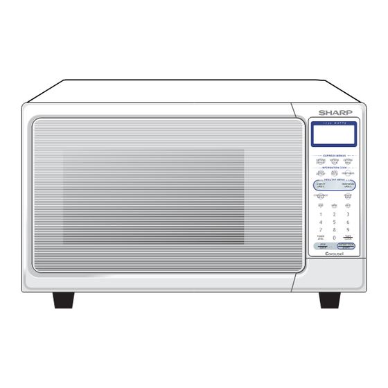
Page 5: Appearance View
R-350J APPEARANCE VIEW 11 2 1. Door open button 8. Touch control panel 2. Door safety latches 9. Liquid crystal display 3. Removable turntable support 10.Coupling 4. Removable turntable tray 11.Waveguide cover 5. Oven lamp 12.Power supply cord 6. See through door 13.Door hinges... -
Page 6: Operation Sequence
R-350J OPERATION SEQUENCE OFF CONDITION opened after the cooking cycle has been interrupted, because the relay RY1 stays closed. Shown in the Closing the door activates all door interlock switches display is the remaining time. (1st. latch switch and 2nd. interlock relay control switch). -
Page 7: Function Of Important Components
R-350J FUNCTION OF IMPORTANT COMPONENTS OVEN TEMPERATURE FUSE DOOR OPEN MECHANISM The temperature fuse, located on the top of the oven he door is opened by pushing the open button on the cavity, is designed to prevent damage to the oven by fire. -
Page 8: Servicing And Troubleshooting Guide
If the water remains cold carry out 3D checks and re- examine the connections to the component being Sharp recommend that wherever possible fault-finding tested. is carried out with the supply disconnected. It may in, some cases, be necessary to connect the supply after... - Page 9 R-350J CK = Check / RE = Replace TEST PROCEDURE A B C D E E F G G H K L M N RECK CK RE CK CKCK CK CK POSSIBLE CAUSE DEFECTIVE PARTS PROBLEM CONDITION Home fuse blows when power supply cord is plugged into wall outlet.
-
Page 10: Test Procedure
R-350J TEST PROCEDURES PROCEDURE COMPONENT TEST LETTER MAGNETRON TEST NEVER TOUCH ANY PART IN THE CIRCUIT WITH YOUR HAND OR AN INSULATED TOOL WHILE THE OVEN IS IN OPERATION. CARRY OUT 3D CHECK. Isolate the magnetron from high voltage circuit by removing all leads connected to filament terminal. - Page 11 R-350J TEST PROCEDURES PROCEDURE COMPONENT TEST LETTER ± JUDGEMENT: The measured output power should be at least 15 % of the rated output power. CAUTION: 1°C CORRESPONDS TO 120 WATTS REPEAT MEASUREMENT IF THE POWER IS INSUFFICIENT. 1000g 1000g 1000g T1˚C...
- Page 12 R-350J TEST PROCEDURES PROCEDURE COMPONENT TEST LETTER C. A normal capacitor shows continuity for a short time (kick) and then a resistance of about 10MΩ after it has been charged. D. A short-circuited capacitor shows continuity all the time. E. An open capacitor constantly shows a resistance about 10 MΩ because of its internal 10MΩ resistance.
- Page 13 R-350J TEST PROCEDURES PROCEDURE COMPONENT TEST LETTER 2. If the fuse F10A is blown when the door is opened, check the 1st. latch switch, 2nd. interlock relay and monitor switch. If the fuse F10A is blown by incorrect door switching replace the defective switch(s) and the fuse F10A.
- Page 14 R-350J TEST PROCEDURES PROCEDURE COMPONENT TEST LETTER KEY UNIT TEST If the display fails to clear when the STOP/CLEAR pad is depressed, first verify the flat ribbon cable is making good contact, verify that the 2nd. interlock relay control switch operates properly; that is the contacts are closed when the door is closed and open when the door is open.
-
Page 15: Touch Control Panel
R-350J TEST PROCEDURES PROCEDURE COMPONENT TEST LETTER NOTE: *At the time of making these repairs, make a visual inspection of the varistor. Check for burned damage and exam- ine the transformer with a tester for the presence of layer short-circuit (check the primary coil resistance). - Page 16 R-350J The I/O signal of the LSI is detailed in the following table. Pin No. Signal Description COM5 Common data signal : COM11. Connected to LCD signal COM11. COM4 Common data signal : COM12. Connected to LCD signal COM12. COM3 Common data signal : COM13.
- Page 17 R-350J Pin No. Signal Description Key strobe signal. Signal applied to touch-key section. A pulse signal is input to AIN7, P14, P15, P16 and P17 terminal while one of G3 line keys on key matrix is touched. Key strobe signal.
- Page 18 R-350J Pin No. Signal Description COM13 Common data signal : COM3. Connected to LCD signal COM3. COM14 Common data signal : COM2. Connected to LCD signal COM2. COM15 Common data signal : COM1. Connected to LCD signal COM1. 75-102 Terminal not used.
- Page 19 R-350J TOUCH CONTROL PANEL SERVICING 1. Precautions for Handling Electronic Components A. On some models, the power supply cord between the touch This unit uses CMOS LSI in the integral part of the circuits. control panel and the oven itself is so short that the two can’t When handling these parts, the following precautions should be separated.
-
Page 20: Component Replacement And Adjustment Procedure
Please refer to ‘OVEN PARTS, CABINET PARTS, CONTROL PANEL PARTS, DOOR PARTS’, when carrying out any of the following removal procedures: WARNING FOR WIRING 3) Sharp edge: To prevent an electric shock, take the following manners. Bottom plate, Oven cavity, Waveguide flange, Chassis 1. -
Page 21: Magnetron Removal
R-350J 4. Disconnect the filament lead (short one) of the power 8. Disconnect the high voltage fuse from the capacitor. The high transformer from the high voltage capacitor. voltage fuse is now free. 5. Remove the one (1) screw holding capacitor holder to bottom 9. -
Page 22: Turntable Motor Removal
8. After replacement use the one (1) screw (XHPSD40P08K00) 4. Where the corners have been snipped off bend corner areas to fit the turntable motor cover. flat. No sharp edges must be evident after removal of the turntable motor cover. COOLING FAN MOTOR REMOVAL REMOVAL 8. - Page 23 R-350J 5. Now, the power supply cord is free. 2. Install the earth wire lead of power supply cord to the oven cavity back plate with one (1) screw and tight the screw. Re-install 3. Connect the brown and blue wire leads of power supply cord 1.
-
Page 24: Door Replacement
R-350J DOOR REPLACEMENT REMOVAL 2. Deviation of door alignment from horizontal line of cavity face 1. Disconnect the power supply cord. plate is to be less than 1.0mm. 2. Open button and open the door slightly. 3. Door is positioned with its face pressed toward cavity face 3. -
Page 25: Microwave Measurement
R-350J MICROWAVE MEASUREMENT After adjustment of door latch switches, monitor switch Recommended instruments are: and door are completed individually or collectively, the NARDA 8100 following leakage test must be performed with a survey NARDA 8200 instrument and it must be confirmed that the result meets... -
Page 26: Wiring Diagram
R-350J SCHEMATIC NOTE: CONDITION OF OVEN 1. DOOR CLOSED NOTE: " " indicates components with potentials above 250V. 2. CLOCK APPEARS ON DISPLAY TEMPERATURE NOISE FILTER FUSE 150˚C (OVEN) FUSE F10A N.O. COM. RY-2 2ND. INTERLOCK RELAY CONTROL UNIT CAPACITOR 1.13µ... -
Page 27: Pictorial Diagram
R-350J... -
Page 28: Power Unit Circuit
R-350J CN-C 12PIN LEAD WIRE HARNESS Q2 2SB1238 R4 27 R5 4.7k D1-D4 1N4002 CN-A 1SS270A 1SS270A – – R2 510 1w R3 390 1w SP1 PKM22EPT Q3 KRC243M BUZZER R6 3.3k OVEN LAMP TURNTABLE OVEN LAMP MOTOR TURNTABLE FAN MOTOR MOTOR –... -
Page 29: Cpu Unit Circuit
R-350J COM8 COM7 COM6 COM5 COM4 COM3 COM2 COM1 SEG1 SEG2 SEG3 SEG4 SEG5 SEG6 SEG7 SEG33 COM13 SEG8 SEG32 COM12 SEG9 SEG31 COM11 SEG10 SEG30 COM10 SEG11 SEG29 COM9 SEG12 SEG28 COM8 SEG13 SEG27 AIN0 SEG14 SEG26 AIN1 SEG15... -
Page 30: Printed Wiring Board
R-350J (RED) (GREEN) CN - C SH - B SH - A B R1 (CN - B) (J2) (R9) (D10) (CN - D) (J1) CN - A Figure S-3. Printed Wiring Board of Power Unit... -
Page 31: Parts List
R-350J PARTS LIST ∆ Note: The parts marked " " may cause undue microwave exposure. The parts marked "*" are used in voltage more than 250V. REF. NO. PART NO. DESCRIPTION Q'TY CODE ELECTRIC PARTS 1- 1 QSW-MA147WRZZ 1st. latch/2nd. interlock relay control relay conrol switch... - Page 32 R-350J ∆ Note: The parts marked " " may cause undue microwave exposure. The parts marked "*" are used in voltage more than 250V. REF. NO. PART NO. DESCRIPTION Q'TY CODE 5- 4 HPNL-A811WRRZ Door screen ∆ 5- 5 LSTPPA188WRF0...
- Page 33 R-350J 7-10 OVEN AND CABINET PARTS 7-10 7-10 1-13 1-12 4-15 4-12 7-11 4-16 4-13 7-10 7-10 7-10 4-19 1-11 4-14 4-17 4-12 7-12 4-10 4-18 1-10 4-11 4-12 1-14 7-10 4-12 7-10...
- Page 34 R-350J CONTROL PANEL PARTS 3-2-1 DOOR PARTS MISCELLANEOUS Actual wire harness may be different from illustration.
-
Page 35: Packing And Accessories
R-350J PACKING AND ACCESSORIES TOP PAD ASSEMBLY FPADBA541WRKZ DOOR PROTECTION SHEET SPADPA204WRE0 PLASTIC BAG SSAKHA034WRE0 6-6 INSTRUCTION BOOK BOTTOM PAD ASSEMBLY 6-2 TURNTABLE TRAY FPADBA542WRKZ 6-1 TURNRTABLE SUPPORT INTO THE OVEN CAVITY PACKING CASE SPAKCE111WREZ Not replaceable items. TRAY PAD ASSY... - Page 36 R-350J COPYRIGHT © 2004 BY SHARP CORPORATION ALL RIGHTS RESERVED. No part of this publication may be reproduced, stored in retrieval systems, or transmitted in any form or by any means, electronic, mechanical, photocopying, recording, or otherwise, without prior written permission of the publisher.
Need help?
Do you have a question about the R-350J and is the answer not in the manual?
Questions and answers