Sign In
Upload
Manuals
Brands
Xantrex Manuals
Inverter
PROsine 2.0
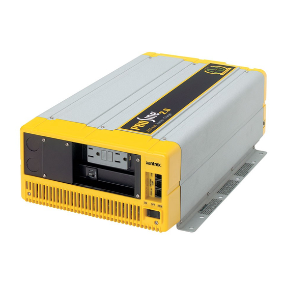
Xantrex PROsine 2.0 Inverter/Charger Manuals
Manuals and User Guides for Xantrex PROsine 2.0 Inverter/Charger. We have
2
Xantrex PROsine 2.0 Inverter/Charger manuals available for free PDF download: User Manual
Xantrex PROsine 2.0 User Manual (164 pages)
2000 watt Inverter Charger
Brand:
Xantrex
| Category:
Inverter
| Size: 3 MB
Table of Contents
Information about Your System
4
Default Values for Prosine 2.0 System
5
Table of Contents
7
List of Figures
15
Important Safety Instructions
17
General Safety Precautions
17
Explosive Gas Precautions
18
Precautions When Working with Batteries
18
Materials List
20
Fig Title
21
Prosine 2.0 Materials as Shipped
21
Warranty
22
Return Material Authorization Policy
23
Return Material Procedure
23
Contents & Organization of this Manual
24
Related Documents
25
Section 1 Introduction
27
The Heart of a Sophisticated, Independent Power System
28
Inverting
28
Charging
29
Power System Management
30
Section 2 Product Orientation
33
Inverter•Charger Features
34
Inverter•Charger: AC End
34
AC End View (Blank Panel Option)
34
AC Panel Options
35
Panel Equipped with GFCI and Circuit Protector
35
Inverter•Charger: DC End
36
DC Terminal Covers
36
DC Terminal Cover: Top View on Left; Bottom View on Right
36
Display Panel Features
37
Prosine 2.0 Inverter•Charger Display Panel
37
DISPLAY Mode Switch
38
INVERTER Switch
38
INVERTER Leds
38
CHARGER Switch
39
CHARGER Leds
39
LCD Panel
40
Data Display Mode
40
Configuration Mode
40
Menu Navigation and Data Selection Buttons
41
Battery Temperature Sensor
42
Section 3 Installation
43
Safety Instructions
43
Installation Codes
43
Installation Tools and Materials
44
Installation Procedures
44
Step 1: Designing the Installation
45
Typical Recreational Vehicle and Fleet Vehicle Installation
45
Table 1 Default Values: Inverter•Charger
47
Table Title
47
Table 1 Required AC Wire Size Vs Breaker Rating
47
Table 2 Required DC Cable and Fuse Size
47
Table 3 Tested GFCI Models
48
Step 2: Choosing a Location for the Inverter•Charger
49
Step 3: Mounting the Inverter•Charger
50
Approved Mounting Orientations
50
Step 4: Connecting the AC Input Wires
51
General AC Wiring Considerations
51
Interior of AC Wiring Compartment
51
AC Input Connections
52
Incoming AC Cable (Top, Cutaway View of Wiring Compartment)
52
Step 5: Configuring the Output Neutral Bonding System
53
AC Output Neutral-To-Ground Bonding System
53
Table 4 AC Output Neutral-To-Ground Bonding Screw Settings
54
Step 6: Connecting the AC Output Wires
55
Connections for Hardwire Option
55
Connections for Single Hardwire Output with GFCI
56
Single Hardwire Output with GFCI
56
12 Hardwire AC Output Option (Top, Cutaway View of Wiring Compartment) 29
56
Step 7: Connecting the DC Cables
57
DC End
57
DC Cable Connections
59
DC Grounding
59
Step 8: Mounting the Display Panel
60
Step 9: Connecting the Battery Temperature Sensor
61
Mounting Options
61
Mounting to the Negative Battery Terminal
61
BTS Attached to Negative Battery Terminal
61
Mounting to the Side of the Battery Case
62
BTS Attached to Battery Case
62
Step 10: Connecting the Remote Shutdown
64
Materials Required
64
Installation Steps
64
Next Steps
65
Cabling Details for Remote Shutdown Feature
65
Schematic for Remote Shutdown Feature
65
Section 4 Configuration
67
Part 1: General Configuration Information
68
Entering Configure Mode
68
Entering Installer-Only Mode
68
Changing Settings
69
Changing Settings: Example 1
69
Changing Settings: Example 2
69
Part 2: Configuration Menus and Screens
70
Table 5 Menu Structure-Overview
71
Part 3: Configuration Options
72
Clear Errors in Prosine
72
Configure Prosine-Basic Menu
73
Configure Prosine-Advanced Menu
74
Configure Display Panel Menu
77
Configure Battery Menu
78
Battery Size
79
Battery Type
79
Charger Mode
82
Diagnostics Menu
84
Next Steps
85
Section 5 Operation
87
Part 1: System Startup Check
88
Part 2: Operating Considerations
89
Fan Operation
89
On/Off/Remote Control of Inverter•Charger Operation
89
Part 3: Operation in Inverter Mode
90
Load Sensing Mode
90
Operating Limits for Inverter Operation
90
Power Output
90
Input Voltage
91
Table 6 Prosine Operating Voltage Limits
91
Part 4: Operation in Charger Mode
92
Operation in Equalization Mode
93
Equalization Procedure
93
Operating Limits for Charger Operation
94
Power Share
94
Part 5: Display Mode Screens
95
Section 6. Troubleshooting
97
General Troubleshooting Guidelines
98
Shutdown / Restart Without Error Message
99
AC Bad Causes
100
Table 7 AC Bad Causes
100
Warning Messages
101
Table 8 Warning Messages
101
Error Messages
104
Table 9 Error Messages
104
Display Panel Faults
106
Table 10 Panel Faults
106
Inverter Applications
107
Resistive Loads
107
Motor Loads
107
Problem Loads
107
Section 7 Series Operation
109
Part 1: Designing a Series System
110
System Overview
110
System Components
110
Two Inverter•Charger Series Operation System
111
AC Input
112
AC Output
112
Battery Disconnect and Over-Current Protection Requirements
112
Series Sync Connection
112
Part 2: Installing a Series System
113
Connecting AC Input Wiring
113
Connecting AC Output Wiring
114
Configuring the Inverter Output Neutral Bonding
114
Connecting the DC Cables
115
Connecting the DC Ground
115
Installing the Display Panels
116
Installing the Battery Temperature Sensors
116
Installing the Series Sync Cable
116
Part 3: Configuring a Series System
117
Part 4: Series System Startup Test
118
Part 5: Series System Operation
119
Invert Mode
119
Charge Mode
119
Appendix A Specifications
121
Electrical Specifications: Invert Mode
122
Electrical Specifications: Charge Mode
122
Environmental Specifications
123
System
123
Regulatory Approvals
123
Inverter Overload Operation
124
Typical Inverter Efficiency
124
Invert Power Derating Vs Ambient Temperature
125
Prosine Charger Output Current Vs AC Input Voltage
125
Inverter•Charger Dimensions
126
Appendix B Typical System Diagrams
127
Residential Backup System
128
22 Residential Backup System
129
Marine System
129
Typical Marine System
129
Appendix C Batteries
131
Terminology
131
Battery Types
132
Starting Batteries
132
Deep-Cycle Batteries
132
Sealed Gel-Cell
133
Environment
133
Location
133
Enclosures
134
Temperature
134
Battery Bank Sizing
135
Estimating Battery Requirements
136
Battery Bank Sizing Example
137
Table 11 Battery Sizing Example
137
Table 12 Battery Sizing Worksheet
138
Monthly Battery Maintenance
139
Preparation
139
Clothing
139
Tools
140
Equipment
140
Supplies
140
Procedure
140
Cabling & Hook-Up Configurations
142
Parallel Connection
142
Batteries Connected in Parallel
142
Series Connection
143
Batteries Connected in Series
143
Series-Parallel and "Cross-Tied" Connections
144
Series-Parallel and Cross-Tied Connections
144
Appendix D Battery Charging Reference
145
Multi-Stage Charging
146
Three-Stage Charging Profile
146
Bulk Charge
147
Absorption Charge
147
Overcharge
147
Float Charge
147
Equalization Charge
148
Two-Stage Charging Profile
148
Battery Charging Times
149
Battery Charging and Equalization Guide
150
Table 13 Battery Charging and Equalization Guide-General
150
Prosine 2.0 Charge Algorithms
151
Table 14 Charge Algorithms
151
Battery Type-Charge Algorithm Guide
152
Table 15 Battery Type - Charge Algorithm Guide
152
Index
155
Advertisement
Xantrex PROsine 2.0 User Manual (148 pages)
Inverter/Charger
Brand:
Xantrex
| Category:
Inverter
| Size: 3 MB
Table of Contents
About this Manual
5
Abbreviations and Acronyms
7
Conventions Used
7
Related Documents
7
Related Information
7
Important Safety Instructions
9
Explosive Gas Precautions
10
Precautions When Working with Batteries
10
Table of Contents
13
1 Introduction
21
Your Prosine
22
The Heart of a Sophisticated, Independent Power System
23
Inverting
23
Charging
24
Power System Management
25
Materials List
26
Figure 1-1 Prosine Materials as Shipped
28
Default Values for the Prosine System
29
Table 1-1 Prosine Default Values
29
2 Product Orientation
31
Prosine Features
32
AC End
32
Figure 2-1 AC End View (Blank Panel Option)
32
AC Panel Options
33
Figure 2-2 Panel Equipped with GFCI and Circuit Protector
33
DC End
34
Figure 2-3 DC End
34
DC Terminal Covers
35
Figure 2-4 DC Terminal Cover: Top View on Left; Bottom View on Right
35
Display Panel Features
36
Figure 2-5 Prosine Display Panel
36
DISPLAY Mode Switch
37
INVERTER Leds
38
INVERTER Switch
38
CHARGER Leds
39
CHARGER Switch
39
Configuration Mode
40
Data Display Mode
40
LCD Panel
40
Menu Navigation and Data Selection Buttons
41
Battery Temperature Sensor
42
Figure 2-6 Battery Temperature Sensor
42
3 Installation
43
Safety Instructions
44
Installation Codes
44
Installation Tools and Materials
45
Installation Procedures
45
Step 1: Designing the Installation
46
Figure 3-1 Typical Recreational Vehicle and Fleet Vehicle Installation
46
Table 3-1 Required AC Wire Size Vs Breaker Rating
48
Table 3-2 Required DC Cable and Fuse Size
49
Table 3-3 Tested GFCI Models
50
Step 2: Choosing a Location for the Prosine
51
Step 3: Mounting the Prosine
52
Figure 3-2 Approved Mounting Orientations
52
Step 4: Connecting the AC Input Wires
53
General AC Wiring Considerations
53
Figure 3-3 Interior of AC Wiring Compartment
53
AC Input Connections
54
Figure 3-4 Incoming AC Cable (Top, Cutaway View of Wiring Compartment)
54
Step 5: Configuring the Output Neutral Bonding System
55
AC Output Neutral-To-Ground Bonding System
55
Table 3-4 AC Output Neutral-To-Ground Bonding Screw Settings
56
Step 6: Connecting the AC Output Wires
57
Connections for Hardwire Option
57
Figure 3-5 Hardwire AC Output Option (Top, Cutaway View of Wiring Compartment)
57
Connections for Single Hardwire Output with GFCI
58
Figure 3-6 Single Hardwire Output with GFCI
58
Step 7: Connecting the DC Cables
59
Figure 3-7 DC End
59
DC Grounding
61
Figure 3-8 DC Cable Connections
61
Step 8: Mounting the Display Panel
62
Step 9: Connecting the Battery Temperature Sensor
63
Mounting Options
63
Mounting to the Negative Battery Terminal
63
Figure 3-9 BTS Attached to Negative Battery Terminal
63
Mounting to the Side of the Battery Case
65
Figure 3-10 BTS Attached to Battery Case
65
Step 10: Connecting the Remote Shutdown
66
Installation Steps
66
Next Steps
67
Figure 3-11 Cabling Details for Remote Shutdown Feature
67
Figure 3-12 Schematic for Remote Shutdown Feature
67
4 Configuration
69
Part 1: General Configuration Information
70
Entering Configure Mode
70
Entering Installer-Only Mode
70
Changing Settings
71
Resetting to Factory Defaults
72
Part 2: Configuration Menus and Screens
72
Table 4-1 Menu Structure-Overview
73
Part 3: Configuration Options
74
Clear Errors in Prosine
74
Configure Prosine-Basic Menu
75
Menu Choices or Information Displayed
75
Configure Prosine-Advanced Menu
76
Menu Choices or Information Displayed
76
Configure Display Panel Menu
79
Menu Choices or Information Displayed
79
Configure Battery Menu
80
Menu Choices or Information Displayed
81
Diagnostics Menu
85
Menu Choices or Information Displayed
85
Next Steps
86
5 Operation
87
Part 1: System Startup Check
88
Part 2: Operating Considerations
89
Fan Operation
89
On/Off/Remote Control of Prosine Operation
89
Hysteresis
89
Part 3: Operation in Inverter Mode
91
Load Sensing Mode
91
Operating Limits for Inverter Operation
91
Power Output
91
Input Voltage
92
Table 5-1 Prosine Operating Voltage Limits
92
Part 4: Operation in Charger Mode
93
Operation in Equalization Mode
93
Equalization Procedure
94
Operating Limits for Charger Operation
95
Power Share
95
Part 5: Display Mode Screens
96
6 Troubleshooting
97
General Troubleshooting Guidelines
98
Shutdown / Restart Without Error Message
99
Resetting Prosine Operation
99
AC Bad Causes
99
Table 6-1 AC Bad Causes
99
Warning Messages
100
Table 6-2 Warning Messages
100
Error Messages
102
Table 6-3 Error Messages
102
Display Panel Faults
105
Table 6-4 Panel Faults
105
Unexplained Faults
106
Table 6-5 Unexplained Faults
106
Inverter Applications
107
Resistive Loads
107
Motor Loads
107
Long Transfer Times
107
Problem Loads
108
7 Series Operation
109
Designing a Series System
110
System Overview
110
System Components
110
Figure 7-1 Two Prosine Series Operation System
111
AC Input
112
AC Output
112
Battery Disconnect and Over-Current Protection Requirements
112
Series Sync Connection
112
Installing a Series System
113
Connecting AC Input Wiring
113
Connecting AC Output Wiring
114
Configuring the Inverter Output Neutral Bonding
114
Connecting the DC Cables
114
Connecting the DC Ground
115
Installing the Display Panels
115
Installing the Battery Temperature Sensors
115
Installing the Series Sync Cable
116
Configuring a Series System
117
Series System Startup Test
118
Series System Operation
119
Invert Mode
119
Charge Mode
119
Specifications
121
Electrical Specifications: Invert Mode
122
Electrical Specifications: Charge Mode
123
Environmental Specifications
124
System
124
Regulatory Approvals
124
Inverter Overload Operation
125
Typical Inverter Efficiency
125
Invert Power Derating Vs. Ambient Temperature
126
Prosine Charger Output Current Vs. AC Input Voltage
126
Prosine Dimensions
127
Figure A-1 Prosine Dimensions
127
System Diagrams
129
Residential Backup System
130
Figure B-1 Residential Backup System
130
Marine System
131
Figure B-2 Typical Marine System
131
C Charging Algorithms
133
Charge Algorithms
133
Battery Type-Charge Algorithm Guide
133
Table C-1 Charge Algorithms
134
Table C-2 Battery Type - Charge Algorithm Guide
135
Warranty and Return Information
137
Return Material Authorization Policy
139
Out of Warranty Service
139
Return Procedure
139
Information about Your System
140
Index
146
Advertisement
Related Products
Xantrex 230 VAC/50
Xantrex xpower 200W
Xantrex Freedom X 2000 120VAC 12VDC
Xantrex Freedom X 2000 120VAC 24VDC
Xantrex Freedom 20D
Xantrex Prosine PS3.0 and
Xantrex Prosine PS2.5 and
Xantrex Prosine 1800
Xantrex Prosine 1800i
Xantrex Prosine 1000i
Xantrex Categories
Inverter
Power Supply
Battery Charger
Power Pack
Controller
More Xantrex Manuals
Login
Sign In
OR
Sign in with Facebook
Sign in with Google
Upload manual
Upload from disk
Upload from URL