Table of Contents
Advertisement
Quick Links
NOTE:
Please read all instructions
carefully before using this
product
Table of Contents
Safety Notice
Hardware Identifier
Assembly Instruction
Parts List
Computer
Warranty
Ordering Parts
Model
PL 960
Retain This
Manual for
Reference
10-30-03
OWNER'S
MANUAL
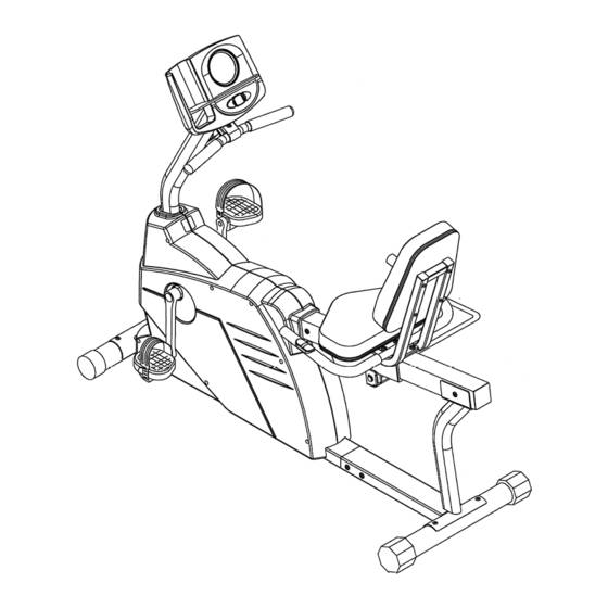
MARCY Recumbent Bike
14777 DON JULIAN RD., CITY OF INDUSTRY, CA 91746
Tel: (800) 999-8899 Fax: (626) 961-9966
www.impex-fitness.com
info@impex-fitness.com
PL-960
IMPEX INC.
Advertisement
Table of Contents

Related Manuals for Impex MARCY PL-960


Summary of Contents for Impex MARCY PL-960
- Page 1 NOTE: Please read all instructions carefully before using this product MARCY Recumbent Bike Table of Contents PL-960 Safety Notice Hardware Identifier Assembly Instruction Parts List Computer Warranty Ordering Parts Model PL 960 Retain This Manual for Reference 10-30-03 IMPEX INC.
-
Page 2: Table Of Contents
WARRANTY....................…. ORDERING PARTS..................… BEFORE YOU BEGIN Thank you for selecting the MARCY Recumbent Bike PL-960 by IMPEX INC. For your safety and benefit, read this manual carefully before using the machine. As a manufacturer, we are committed to provide you complete customer satisfaction. -
Page 3: Important Safety Notices
IMPORTANT SAFETY NOTICE PRECAUTIONS This exercise machine is built for optimum safety. However, certain precautions apply whenever you operate a piece of exercise equipment. Be sure to read the entire manual before you assemble or operate your machine. In particular, note the following safety precautions: 1. -
Page 5: Assembly Instructions
ASSEMBLY INSTRUCTION Tools Required Assembling the Machine: Two Adjustable Wrenches and Allen Wrenches. NOTE: It is strongly recommended two or more people assembling this machine to avoid possible injury. STEP 1 (See Diagram1) A.) Attach the Front Stabilizer (#2) to the Main Frame (#1). Secure it with two M10 x ¾” Allen Bolts (#9). - Page 6 STEP 2 (See Diagram 2) A.) Attach the Computer Post (#4) to the Main Frame (#1). Connect the Middle Computer Sensor Wire (#24) to the Lower Computer Sensor Wire (#25). B.) Connect the Upper Pulse Sensor Wire (#27) to the Middle Pulse Sensor Wire (#28). C.) Connect the Upper Tension Connector (#23) to the bracket on the Lower Tension Connector (#26).
- Page 7 DIAGRAM 2...
- Page 8 HOW TO CONNECT TENSION CONNECTOR Slide the Cable wire from the Upper Tension Connector in between the opening on the wire holder on the Lower Tension Connector. Pull the Upper Tension Connector backward and slide the wire through the slot on the bracket.
- Page 9 STEP 3 (See Diagram 3) A.) Slide the Seat Sliding Frame (#16) onto the Seat Support (#15). B.) Remove the Seat Handle binder. Secure the Seat Handle (#17) with four M8 x 3/8” Allen Bolts (#22). DIAGRAM 3...
- Page 10 STEP 4 (See Diagram 4) A.) Connect the Upper Pulse Sensor Wire (#28) from the Main Frame to the Pulse Sensor Cord (#29). Connect the Pulse Sensor Cord to the Lower Pulse Sensor Wire (#30) on the Seat Sliding Frame (#16). B.) Attach the front of Seat Support (#15) to the Main Frame.
- Page 11 STEP 5 (See Diagram 5) A.) Place the Seat (#18) onto the Seat Sliding Frame (#16). Secure it with four M6 x 5/8” Philips Screws (#20). B.) Attach the Backrest Board (#19) to the Seat Sliding Frame. Secure it with four M6 x 1 3/8”...
- Page 12 STEP 6 (See Diagram 6) A.) Thread the Left Pedal (#7) counter clockwise into the Left Crank (#32). Thread the Right Pedal (#8) clockwise into the Right Crank (#33). DIAGRAM 6...
-
Page 14: Parts List
PARTS LIST KEY NO. DESCRIPTION QUANTITY Main Frame Front Stabilizer Rear Stabilizer Computer Post Front Handle Computer Left Pedal Right Pedal M10 x ¾” Allen Bolt M6 x 3/8” Philips Screw M8 x 5/8” Allen Bolt Ø 5/8” Washer Ø 7/8” Bent Washer Rear Support Seat Support Seat Sliding Frame... -
Page 15: Computer
COMPUTER DETAIL OF OPERATION: SET CLOCK: Once the batteries are installed, the Hour digit starts flashing. Press UP or DOWN button to set the hour and then press ENTER. After the Hour is set, the Minute digit starts flashing. Press UP or DOWN button to set the minute then press ENTER. Note: If you made a mistake or would like to re-set the clock, remove the batteries then start over. -
Page 16: Operating The Computer
Operating the Computer Count Up The computer can be turned on by pressing any of the three keys or by simply pedaling the bike. The values for Time, Dist, and Cal will start from Zero and accumulates upward. To reset all values back to Zero, Press and Hold Down the Enter key for two seconds. -
Page 17: Warranty
IMPEX INC. LIMITED WARRANTY IMPEX Inc. ("IMPEX") warrants this product to be free from defects in workmanship and material, under normal use and service conditions, for a period of two years on the Frame from the date of purchase. This warranty extends only to the original purchaser. IMPEX's obligation under this Warranty is limited to replacing or repairing, at IMPEX's option.
Need help?
Do you have a question about the MARCY PL-960 and is the answer not in the manual?
Questions and answers