Table of Contents
Advertisement
NOTE:
Please read all instructions
carefully before using this
product
Table of Contents
Safety Notice
Hardware Identifier
Assembly Instruction
Parts List
Warranty
Ordering Parts
Model
MP-6000
Retain This
Manual for
Reference
08-19-07
OWNER'S
MANUAL
MARCY PLATINUM
DELUXE SMITH MACHINE
14777 DON JULIAN RD., CITY OF INDUSTRY, CA 91746
Tel: (800) 999-8899 Fax: (626) 961-9966
www.impex-fitness.com
info@impex-fitness.com
MP-6000
®
IMPEX
INC.
Advertisement
Table of Contents

Subscribe to Our Youtube Channel
Related Manuals for Impex MP-6000


Summary of Contents for Impex MP-6000
- Page 1 NOTE: Please read all instructions carefully before using this product MARCY PLATINUM Table of Contents Safety Notice DELUXE SMITH MACHINE Hardware Identifier MP-6000 Assembly Instruction Parts List Warranty Ordering Parts Model MP-6000 Retain This Manual for Reference 08-19-07 OWNER'S MANUAL ®...
-
Page 2: Table Of Contents
EXPLODED DIAGRAM…………………………………………………………….. MULTI-PURPOSE BENCH PARTS LIST………………………………………… WARRANTY....................… ORDERING PARTS..................BEFORE YOU BEGIN Thank you for selecting the MARCY PLATINUM MP-6000 Smith Machine by ® IMPEX INC. For your safety and benefit, read this manual carefully before using the machine. As a manufacturer, we are committed to provide you complete customer satisfaction. -
Page 3: Important Safety Notices
IMPORTANT SAFETY NOTICE PRECAUTIONS This exercise machine is built for optimum safety. However, certain precautions apply whenever you operate a piece of exercise equipment. Be sure to read the entire manual before you assemble or operate your machine. In particular, note the following safety precautions: 1. -
Page 4: Warning Label Placement
WARNING LABEL PLACEMENT The warning labels shown here have been placed on the Cross Brace and Upper Frame. If the labels are missing or illegible, please call customer service at 1-800-888-8899 for replacements. Apply the labels in the location shown. -
Page 5: Smith Machine Hardware Pack
SMITH MACHINE HARDWARE PACK... - Page 6 SMITH MACHINE HARDWARE PACK...
- Page 7 SMITH MACHINE HARDWARE PACK...
-
Page 8: Smith Machine Assembly Instructions
SMITH MACHINE ASSEMBLY INSTRUCTION Tools Required Assembling the Machine: Two Adjustable Wrenches and Allen Wrenches. NOTE: It is strongly recommended two or more people assembling this machine to avoid possible injury. STEP 1 (See Diagram 1) A.) Do not tighten all nuts and bolts until instructed to do so. B.) Attach one Base Frame (#1) to the Left Vertical Frame (#3). - Page 9 DIAGRAM 1...
- Page 10 STEP 2 (See Diagram 2) A.) Attach the Vertical Frame Base (#9) to the Cross Brace (#6) from the bottom. Attach the Rear Vertical Frame (#8) onto the Cross Brace on the top. Align the holes and secure them together with two M10 x 2 3/8” Carriage Bolts (#83), Ø ¾” Washers (#89), and M10 Aircraft Nuts (#90).
- Page 11 STEP 3 (See Diagram 3) A.) Attach the Weight Glide Post (#11) to the bracket on the Vertical Frame Base (#9). Secure it with one 3 1/8” x 1 ¾” Bracket (#31), M10 x 2 ½” Carriage Bolt (#84), Ø ¾” Washer (#89), and M10 Aircraft Nut (#90) to the upper hole, one M10 x 2 ½”...
- Page 12 DAIGRAM 3...
- Page 13 STEP 4 (See Diagram 4) A.) Attach the Butterfly Base (#37) to the Rear Vertical Frame (#8). Secure it with two M10 x 2 ½” Carriage Bolts (#84), Ø ¾” Washers (#89), and M10 Aircraft Nuts (#90). B.) Attach two Swivel Pulley Brackets (#35) to the open brackets on the Rear Vertical Frame (#8).
- Page 14 CABLE LOOP DIAGRAM...
- Page 15 STEP 5 (See Diagram 5 & Cable Loop Diagram) A.) Attach the 142” Upper Cable (#40) to the front opening on the Upper Frame (#7). Attach a Pulley (#59) to the opening. Secure it with one M10 x 2 1/8” Allen Bolt (#79), two Ø 1 1/8” x 3/8” Pulley Bushings (#52), and one M10 Aircraft Nut (#90).
- Page 16 STEP 6 (See Diagram 6 & Cable Loop Diagram) A.) Attach one end of the 86” Butterfly Cable (#42) to the clip on the Right Butterfly (#39). Draw the Cable to the right open Swivel Pulley Bracket (#35). B.) Attach a Small Pulley (#58) to the Swivel Pulley Bracket. Secure it with one M10 x 1 ¾” Allen Bolt (#78), two Ø...
- Page 17 STEP 7 (See Diagram 7 & Cable Loop Diagram) A.) Insert the tip of the 127” Lower Cable (#41) through the opening on the Foot Plate (#26) to the opening on the Vertical Frame Base (#9). B.) Attach a Small Pulley (#58) to the opening. Attach the Foot Plate to the Frame. Align the holes and secure the Foot Plate, Vertical Frame Base, and the Small Pulley with one M10 x 2 ¾”...
- Page 18 DIAGRAM 7...
- Page 19 STEP 8 (See Diagram 8) A.) NOTE: Help of another person is strongly recommended for this step. Place the Lifting Sleeve (#13) in between the two Safety Stop Frames (#16). Align the holes and insert the Weight Bar (#15) all the way through. Center the bar and use the two M8 x 3/8” Allen Bolts (#86) on the two Safety Stop Frame to secure the Weight Bar on each side.
-
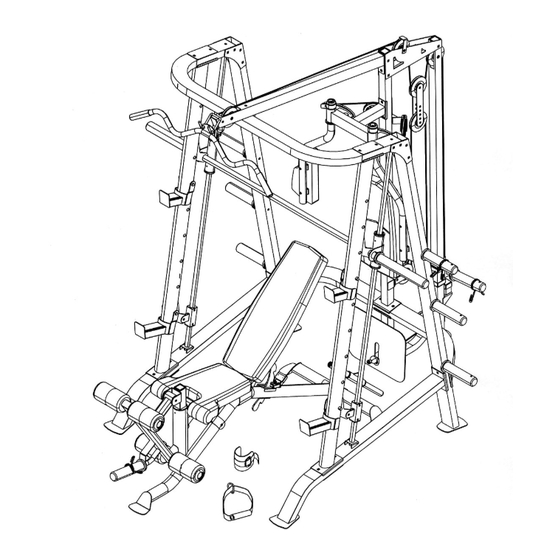
Page 20: Exploded Diagram
SMITH CAGE EXPLODED DIAGRAM... -
Page 21: Smith Machine Parts List
PARTS LIST KEY NO. DESCRIPTION Q’ty Base Frame Ø 1” x 5/8” Pulley Bushing Front Vertical Frame Ø 1 1/8” x 3/8” Pulley Bushing Left Vertical Frame Ø 1” x ¾” Pulley Bushing Right Vertical Frame 1 ½” Sleeve Front Top Beam 5 ¾”... -
Page 22: Multi-Purpose Bench Hardware Pack
MULTI-PURPOSE BENCH HARDWARE PACK... -
Page 23: Multi-Purpose Bench Assembly Instructions
MULTI-PURPOSE BENCH ASSEMBLY INSTRUCTION Tools Required Assembling the Machine: Two Adjustable Wrenches and Allen Wrenches. NOTE: It is strongly recommended this machine be assembled by two or more people to avoid possible injury. STEP 1 (See Diagram 1) A.) Attach the Main Frame (#1) to the Rear Stabilizer (#8). B.) Secure it with two M10 x 3 1/8”... - Page 24 STEP 2 (See Diagram 2) A.) Attach the Seat Support Frame (#11) onto the Main Frame (#1). Secure it with one M10 x 3 1/8” Carriage Bolt (#41), Ø ¾” Washer (#33), and M10 Aircraft Nut (#35). B.) Attach the Main Seat Support (#2) onto the Seat Support Frame. Secure it with one M10 x 3 1/8”...
- Page 25 STEP 3 (See Diagram 3) A.) Align the bracket on the Backrest Adjustment Support (#9) in between the two Backrest Supports (#4). Secure it with four M8 x 1 5/8” Allen Bolts (#37), eight Ø 5/8” Washers (#32), and four M8 Aircraft Nuts (#34). Do not tighten the Nuts and Bolts yet. B.) Insert the Backrest Adjustment Support (#9) into the opening on the Main Frame (#1).
- Page 26 STEP 4 (See Diagram 4) A.) Place the Seat Pad (#15) onto the Front & Rear Seat Brackets (#6 & 7). Secure it with four M8 x 1 5/8” Allen Bolts (#37) and Ø 5/8” Washers (#32). B.) Attach the Backrest Board (#16) to the two Backrest Supports (#4). Secure it with four M8 x 1 5/8”...
- Page 27 STEP 5 (See Diagram 5) A.) Insert the Leg Developer Holder into the Main Seat Support (#2). B.) Thread a Lock Knob (#22) into the Nut on the Main Seat Support (#2) to hold the Leg Developer Holder (#5) at desired height. C.) Attach the Leg Developer (#3) to the open bracket on the Leg Developer Holder.
-
Page 29: Multi-Purpose Bench Parts List
MULTI-PURPOSE BENCH PARTS LIST KEY NO. DESCRIPTION Q’ty Main Frame Main Seat Support Leg Developer Backrest Support Leg Developer Holder Front Seat Bracket Rear Seat Bracket Rear Stabilizer Backrest Adjustment Support Backrest Adjustment Lever Seat Support Frame Foam Tube 4 ¾” Curve Bracket Spring Seat Pad Backrest Board... -
Page 30: Warranty
® IMPEX INC. LIMITED WARRANTY ® IMPEX Inc. ("IMPEX ") warrants this product to be free from defects in workmanship and material, under normal use and service conditions, for a period of two years on the Frame from the date of purchase. This warranty extends only to the original purchaser.
Need help?
Do you have a question about the MP-6000 and is the answer not in the manual?
Questions and answers