Advertisement
NOTE:
Please read all instructions
carefully before using this
product
Table of Contents
Safety Notice
Hardware Identifier
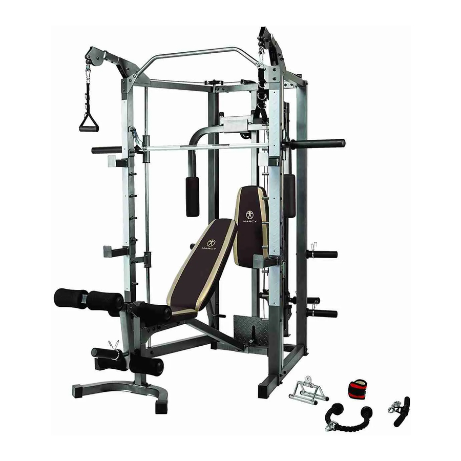
Model
MP 3100
Retain This
Manual for
Reference
01-27-05
OWNER'S
MANUAL
MARCY PLATINUM
14777 DON JULIAN RD., CITY OF INDUSTRY, CA 91746
Tel: (800) 999-8899 Fax: (626) 961-9966
www.impex-fitness.com
info@impex-fitness.com
MP 3100
IMPEX INC.
Advertisement
Table of Contents

Related Manuals for Impex MARCY PLATINUM MP-3100


Summary of Contents for Impex MARCY PLATINUM MP-3100
- Page 1 NOTE: Please read all instructions carefully before using this product MARCY PLATINUM Table of Contents Safety Notice MP 3100 Hardware Identifier Assembly Instruction Parts List Warranty Ordering Parts Model MP 3100 Retain This Manual for Reference 01-27-05 IMPEX INC. OWNER'S 14777 DON JULIAN RD., CITY OF INDUSTRY, CA 91746 MANUAL Tel: (800) 999-8899 Fax: (626) 961-9966...
-
Page 2: Table Of Contents
TABLE OF CONTENTS BEFORE YOU BEGIN..................IMPORTANT SAFETY NOTICES..............HARDWARE PACK…..…..........……………………. ASSEMBLY INSTRUCTIONS...........……………………… 7 EXPLODED DIAGRAM……………………………………………………………... 20 PARTS LIST…………………………………………………………………………. WARRANTY....................…. 23 ORDERING PARTS..................… 23 BEFORE YOU BEGIN Thank you for selecting the MARCY PLATINUM MP3100 by IMPEX INC. For your safety and benefit, read this manual carefully before using the machine. -
Page 3: Important Safety Notices
IMPORTANT SAFETY NOTICE PRECAUTIONS This exercise machine is built for optimum safety. However, certain precautions apply whenever you operate a piece of exercise equipment. Be sure to read the entire manual before you assemble or operate your machine. In particular, note the following safety precautions: 1. -
Page 4: Hardware Pack
HARDEWARE PACK... - Page 5 HARDEWARE PACK...
- Page 6 HARDEWARE PACK...
- Page 7 HARDEWARE PACK...
-
Page 8: Assembly Instructions
ASSEMBLY INSTRUCTION Tools Required Assembling the Machine: Two Adjustable Wrenches and Allen Wrenches. It is recommended two or more people assembling this machine to avoid possible injury. STEP 1 (See Diagram 1) A.) Attach the Left & Right Base Frames (#7 & 8) to the Rear Vertical Frame (#3). Align the holes and secure with two M10 x 2 ½”... - Page 9 STEP 2 (See Diagram 2) A.) Attach the Weight Glide Post (#4) onto the Weight Glide Base (#5). Secure it with four M10 x ¾” Carriage Bolts (#92), ؾ” Washers (#101), and M10 Aircraft Nuts (#98). DO NOT tighten all the Nuts and Bolts yet. B.) Slide the Sliding Weight Post (#15) onto the Weight Glide Post (#4).
- Page 10 STEP 3 (See Diagram 3) A.) Insert a Guide Rod (#18) through the hole on the right Lower Safety Frame (#12) into the hole on the Right Base Frame (#8). Secure the Guide Rod from the bottom with one M10 x 1” Allen Bolt (#87) and Ø ¾” Washer (#101). Slide a Ø 2 ½” x 1” Rubber Bumper (#66) and Glider (#17) from the top onto the Guide Rod (#18).
- Page 11 STEP 4 (See Diagram 4) A.) Attach the Butterfly Base (#10) to the front of Rear Vertical Frame (#3). Attach the Butterfly Pulley Support (#11) to the back. Align the holes and secure them together with two M10 x 2 ½” Carriage Bolts (#91), Ø ¾” Washers (#101), and M10 Aircraft Nuts (#98). B.) Attach the Right Butterfly (#13) to the right hole on the Butterfly Base.
- Page 12 CABLE LOOP DIAGRAM...
- Page 13 STEP 5 (See Diagram 5 & Cable Loop Diagram) A.) Attach a 124” Cable (#38) to the front opening on the Upper Frame (#2). Attach a Pulley (#72) to the opening. Secure it with one M10 x 2 ½” Allen Bolt (#104), two Ø 1” x 5/8” Pulley Bushings (#103), and one M10 Aircraft Nut (#98).
- Page 14 STEP 6 (See Diagram 6 & Cable Loop Diagram) A.) Attach one end of the 79” Butterfly Cable (#39) to the hook on the Left Butterfly (#14). Draw the Cable to the left open bracket on the Butterfly Pulley Support (#11). B.) Attach a Pulley to the bracket and secure it with one M10 x 1 ¾”...
- Page 15 STEP 7 (See Diagram 7 & Cable Loop Diagram) A.) Attach a 124” Cable to the lower opening on the Rear Vertical Frame (#3). Attach a Pulley to the opening. Secure them with one M10 x 2 3/8” Allen Bolt (#86), two Ø 1” x ½”...
- Page 16 DIAGRAM 7...
- Page 17 STEP 8 (See Diagram 8) A.) Attach the Main Seat Support (#28) to the Front & Rear Stabilizers (#29 & 33). Secure each end with two M10 x ¾” Allen Bolts (#83) and Ø ¾” Washers (#101). DIAGRAM 8...
- Page 18 STEP 9 (See Diagram 9) A.) Attach the Backrest Supports (#30) to the pivot on the Main Seat Support (#28). Secure it with one M12 x 5 ¾” Allen Bolt (#82), two Ø 1” Washers (#100), and one M12 Aircraft Nut (#97).
- Page 19 STEP 10 (See Diagram 10) A.) Attach the Leg Developer (#32) to the open bracket on the front of Main Seat Support (#28). Secure it with one M10 x 3 1/8” Allen Bolt (#81), two Ø ¾” Washers (#101), and one M10 Aircraft Nut (#98). Do not over tighten the Nut and Bolt. Make sure the Leg Developer is able to swivel.
- Page 20 STEP 11 (See Diagram 11) A.) Attach the Arm Curl Pad (#44) to the Arm Curl Stand (#34). Secure it with two M8 x ¾” Allen Bolts (#84) and Ø 5/8” Washers (#102). B.) Insert the Arm Curl Stand into the front opening on the Main Seat Support. Use a M18 Lock Knob (#52) to secure the Stand at desired height.
-
Page 21: Exploded Diagram
EXPLODED DIAGRAM... -
Page 23: Parts List
PARTS LIST KEY NO. DESCRIPTION Q’ty Front Vertical Beam 2” Square End Cap Upper Frame 1 ¾” Square End Cap Rear Vertical Frame 1 ½” End Cap Weight Glide Post 2” x 1” End Cap Weight Glide Base 1” Square End Cap Front Top Beam Ø... -
Page 24: Warranty
IMPEX INC. LIMITED WARRANTY IMPEX Inc. ("IMPEX") warrants this product to be free from defects in workmanship and material, under normal use and service conditions, for a period of two years on the Frame from the date of purchase. This warranty extends only to the original purchaser.
Need help?
Do you have a question about the MARCY PLATINUM MP-3100 and is the answer not in the manual?
Questions and answers