Table of Contents
Advertisement
SENS Part Number:
Document Revision:
DCN Number:
Date:
Installation or service questions?
Call SENS at 1.800.742.2326 (303.678.7500)
between 8 a.m. and 5 p.m. (Mountain Time)
Monday through Friday, or visit our website.
Service hotline: 1.800.742.2326
1.303.678.7500
Copyright © Stored Energy Systems LLC 2006
Installation & Operation Manual
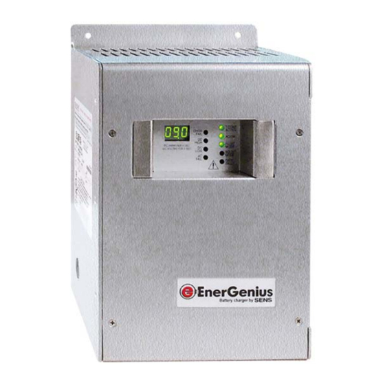
NRG12-10: 12-Volt, 10-Amp Battery Charger
NRG24-10: 24-Volt, 10-Amp Battery Charger
NRG22-10: 12/24-Volt, 10-Amp Battery Charger
101295
L
105749
July 28, 2009
SENS EnerGenius Technical Manual
1840 Industrial Circle
Longmont, CO 80501
Phone:
303.678.7500
800.742.2326
Fax:
303.678.7504
Email:
service@sens-usa.com
Web:
www.sens-usa.com
®
™
1
Advertisement
Table of Contents

Related Manuals for Sens EnerGenius NRG12-10


Summary of Contents for Sens EnerGenius NRG12-10
- Page 1 SENS EnerGenius Technical Manual Installation & Operation Manual NRG12-10: 12-Volt, 10-Amp Battery Charger NRG24-10: 24-Volt, 10-Amp Battery Charger NRG22-10: 12/24-Volt, 10-Amp Battery Charger ® SENS Part Number: 101295 ™ Document Revision: 105749 DCN Number: 1840 Industrial Circle July 28, 2009...
-
Page 2: Important Safety Instructions For Installer And Operator
SENS EnerGenius Technical Manual IMPORTANT SAFETY INSTRUCTIONS FOR INSTALLER AND OPERATOR 1. SAVE THESE INSTRUCTIONS. 2. DO NOT EXPOSE CHARGER TO RAIN OR SNOW. 3. Use of an attachment not recommended or sold by SENS may result in a risk of fire, electric shock, or injury to persons. -
Page 3: Model Number Configuration
MODEL NUMBER CONFIGURATION This manual contains important safety, installation and operating instructions for SENS battery charger model NRG12-10 (configured for 12V,10A only), NRG24-10 (configured for 24V, 10A only) and NRG22-10 (field configurable for 12V or 24V, 10A). Model Number Breakout... -
Page 4: Preparing For Use
SENS EnerGenius Technical Manual 1. PREPARING FOR USE: WARNING: ONLY TRAINED AND QUALIFIED PERSONNEL MAY INSTALL AND SERVICE THIS UNIT. A. INSTALLATION OF THE UNIT MUST COMPLY WITH LOCAL ELECTRICAL CODES AND OTHER APPLICABLE INSTALLATION CODES. B. INSTALLATION MUST BE MADE ACCORDING TO THE INSTALLATION INSTRUCTIONS AND ALL APPLICABLE SAFETY REGULATIONS. - Page 5 SENS EnerGenius Technical Manual FIVE ALARM MODEL SHOWN - SEE PAGE 3 FOR MODEL NUMBER BREAKDOWN See Section 5. C. This unit is permanently connected to the AC circuit and to the battery. An external disconnect device with a minimum of 0.12”(3 mm) pole separation must be located in the AC input to the charger. •...
-
Page 6: Charger Location
SENS EnerGenius Technical Manual ONE ALARM Temperature Sensor -Battery MODEL Alarm Contacts +Battery SHOWN- SEE PAGE 3 Neutral FOR MODEL NUM- 115/230VAC BER BREAKDOWN Grounding Use wire routing devices to hold alarm and Conductor temperature sensor conductors at least 1/4” (6.3 mm) away from power conductors. G. -
Page 7: Neutral Connection
SENS EnerGenius Technical Manual 4. NEUTRAL CONNECTION The grounded circuit conductor (neutral) should be connected to the terminal marked “N” on the input terminal block, TB1. 5. WIRE RATINGS A. All conductors should be rated for use at 90º C or higher. B. -
Page 8: Mounting Location
SENS EnerGenius Technical Manual 7. MOUNTING LOCATION A. See the safety instructions for important information concerning the charger location. B. The charger should be installed in a sheltered area, protected from rain and snow. C. The charger should not be located where temperatures are expected to be colder than -20º C, or hotter than +40º C for operation at rated output current. -
Page 9: Model Number Breakdown
SENS EnerGenius Technical Manual Mounting on a drywall: • Use ¾ in. thick plywood to span two vertical support members in the wall. The plywood sheet normally does not have to be more that 2 ft. by 2 ft. square. •... - Page 10 SENS EnerGenius Technical Manual ONE ALARM MODEL SHOWN - SEE PAGE 3 FOR MODEL NUMBER BREAKDOWN FIGURE 2A FIGURE 2B E. Connect the AC line and neutral conductors at TB1. If there is an identified grounded circuit con- ductor (neutral), attach it to the terminal marked N. TB1 will accept 14-6 AWG (2.5-16 mm ) con- ductors.
- Page 11 SENS EnerGenius Technical Manual F. If the optional alarms are used, connect the alarm wiring to their respective terminals on TB5. Route alarm wiring through the plastic bushing below TB5, keeping the conductors at least ¼ inch (6 mm) away from DC wiring, AC wiring, and the circuit board. The terminals accept 24-16 AWG (0.25-1.5 ) conductors.
-
Page 12: Internal Adjustments
SENS EnerGenius Technical Manual H. Verify that all connections are secure and in the proper locations. Tighten all unused screws on the terminal blocks to secure them against vibration. Ensure all wires are routed so the cover will not pinch them. 11. - Page 13 SENS EnerGenius Technical Manual E. Set the Display Selector jumper to one of the 3 available positions on JP800 (see photograph previous page): • VOLTS – Place the short jumper in the “upper” position next to the word “VOLTS”. The 3-digit LED meter display will show DC Volts only •...
- Page 14 SENS EnerGenius Technical Manual 12. CHECK OUT Green for temperature-corrected charger voltage Green for normal AC input Red for internal charger failure *Red for excessive battery voltage DC Volt/Amp Meter Display *Red for low battery voltage Red for low or missing AC input Green for normal voltage (float charge) Yellow for boost voltage (fast charge) Red for open, wrong voltage, or reversed battery...
-
Page 15: Advanced Design Features
SENS EnerGenius Technical Manual OPERATOR INSTRUCTIONS WARNING: NO OPERATOR SERVICEABLE PARTS INSIDE. DO NOT OPEN. COVER MUST BE IN PLACE DURING USE. USE THIS CHARGER FOR CHARGING LEAD-ACID OR NICKEL-CADMIUM BATTERIES ONLY. A. ADVANCED DESIGN FEATURES Battery Friendly: • Float and boost voltage selectable at install per specific battery vendor recommendations. •... - Page 16 SENS EnerGenius Technical Manual Battery Fault Protection and Alarm: • The battery charger automatically checks the battery voltage before power-on startup. If the battery voltage is either too high or too low, the charger enters a “lockout” period for approximately 10 seconds before attempting an automatic restart.
- Page 17 SENS EnerGenius Technical Manual ITEM TEXT Meaning Troubleshooting CHGR FAIL Charger Fail Charger unable to provide charging current to battery. Replace unit. AC input voltage is too low to supply proper cur- rent when load is applied. Control board is damaged and should be re- placed.
-
Page 18: Normal Set Up
SENS EnerGenius Technical Manual NORMAL SET UP: Apply AC power by closing the branch circuit breaker and any other disconnect devices. 2. The meter display should light immediately after power on. The green AC/ ON LED should be lighted. If a temperature sensor is present, either internal or remote, the green T-COMP (Temperature Compensation) LED should be lighted.
Need help?
Do you have a question about the EnerGenius NRG12-10 and is the answer not in the manual?
Questions and answers