Table of Contents
Advertisement
SENS Part Number:
Document Revision:
DCN Number:
Date:
MADE IN U.S.A.
PATENTED U.S. 9,270,140; 9,385,556; 9,413,186; 9,509,164
Installation or service questions?
Call SENS at 1.800.742.2326 (303.678.7500)
between 8 a.m. and 5 p.m. (Mountain Time)
Monday through Friday, or visit our website.
Service hotline: 1.800.742.2326
Copyright © Stored Energy Systems LLC 2007-2014
1.303.678.7500
Installation & Operation Manual
IQ Case Size Q1
12V/12-50A
120V/6-25A
240V/6-12A
101308-1
R
107186
January 16, 2017
24V/6-50A
48V/6-50A
SENS IQ Technical Manual
STORED ENERGY SYSTEMS
1840 Industrial Circle
Longmont, CO 80501
Phone:
303.678.7500
800.742.2326
Fax:
303.678.7504
Email:
service@sens-usa.com
Web:
www.sens-usa.com
®
1
Advertisement
Table of Contents
Troubleshooting

Related Manuals for Sens Q012-012


Summary of Contents for Sens Q012-012
- Page 1 PATENTED U.S. 9,270,140; 9,385,556; 9,413,186; 9,509,164 Email: service@sens-usa.com Installation or service questions? Web: www.sens-usa.com Call SENS at 1.800.742.2326 (303.678.7500) between 8 a.m. and 5 p.m. (Mountain Time) Monday through Friday, or visit our website. Service hotline: 1.800.742.2326 Copyright © Stored Energy Systems LLC 2007-2014 1.303.678.7500...
-
Page 2: Table Of Contents
SENS IQ Technical Manual TABLE OF CONTENTS IMPORTANT SAFETY INSTRUCTIONS FOR INSTALLER AND OPERATOR ....4 QUICK INSTALLATION GUIDE ....................5 PERFORMANCE SPECIFICATIONS ..................6 MODEL NUMBER CONFIGURATION ..................7 MECHANICAL INSTALLATION ....................7 Lifting ............................7 Charger Mounting Options ......................7 Ventilation ............................ - Page 3 SENS IQ Technical Manual LIST OF TABLES AND FIGURES Figure 1: Typical wiring diagram for IQ battery chargers ................8 Figure 2: Input, output and alarm wiring locations ..................9 Table 1: AC Input Current and AC/DC Circuit Breaker Current Ratings ..........10 Table 2: AC Input Wire Gauge Ratings .....................
-
Page 4: Important Safety Instructions For Installer And Operator
Review cautionary markings on these products. Use of an attachment not recommended or sold by SENS may result in a risk of fire, electric shock, or injury to persons . -
Page 5: Quick Installation Guide
Read all cautionary warnings in Section 1. Remove the charger from the packaging and inspect for damage. See Section 5.1 for information on moving and lifting the charger. Notify SENS immediately (1-800-742-2326) if damage from shipping is evident. See Section 5.2 for mounting options. -
Page 6: Performance Specifications
The digital load sharing cable should never be connected when two chargers are each connected to different batteries. PERFORMANCE SPECIFICATIONS See IQ Product Data Sheet and Product Specification on SENS website (www.sens-usa.com) for detailed per- formance specifications. Service Hotline: 1.800.742.2326... -
Page 7: Model Number Configuration
SENS IQ Technical Manual MODEL NUMBER CONFIGURATION Nominal DC output Rated output current Agency Feature package Alarm Special Option Parameter Code Value Parameter Code Value Nominal Agency 12 volts nominal UL & C-UL listed (60 Hz input units) DC output marks UL &... -
Page 8: Electrical Installation
SENS IQ Technical Manual ELECTRICAL INSTALLATION WARNING: BEFORE ELECTRICAL INSTALLATION, ENSURE THE FOLLOWING: A. AC MAINS SUPPLY CIRCUIT IS DE-ENERGIZED. B. AC INPUT BREAKER ON THE CHARGER IS OPENED C. DC OUTPUT BREAKER ON THE CHARGER IS OPENED D. BATTERY DISCONNECT, IF USED, IS OPENED (BATTERY REMOVED FROM DC BUS). -
Page 9: Ac Input Connections
SENS IQ Technical Manual AC Input Connections The battery charger is designed to be permanently connected to an appropriately rated single phase, grounded AC mains circuit. Wiring used must be sized appropriately for the charger input current and must be selected to meet any applicable local codes (see TABLE 1 for charger circuit breaker ratings and TABLE 2 for recommended wire gauges). -
Page 10: Table 1: Ac Input Current And Ac/Dc Circuit Breaker Current Ratings
SENS IQ Technical Manual Table 1: AC Input Current and AC/DC Circuit Breaker Current Ratings Charger Rated AC Input Current *AC Input Branch Circuit Breaker Charger Input Breaker Charger Model Ratings Current Ratings Output Breaker 480V 120/208/240V 400V 480V 120V... -
Page 11: Dc Output Connections
SENS IQ Technical Manual DC Output Connections WARNING: OBSERVE PROPER POLARITY WHEN CONNECTING THE BATTERY CIRCUIT TO THE CHARGER. FAILURE TO DO SO COULD RESULT IN EXPLOSION AND DAMAGE TO THE BATTERY CHARGER. SHOULD THE BATTERY CONNECTIONS BE REVERSED, A BEEPING TONE WILL BE HEARD WHEN AC POWER IS APPLIED. -
Page 12: Alarm Wiring
SENS IQ Technical Manual Alarm Wiring WARNING: FOR 12V AND 24V OUTPUT CHARGERS, CONNECT ALARM TERMINALS ONLY TO LOW VOLTAGE LIMITED ENERGY (“CLASS 2” or “CLASS 3”) CIRCUITS. ALARM AND PILOT RELAYS ARE RATED 30VDC/VAC AT 2.0A. FOR 48V AND HIGHER OUTPUT CHARGERS, ALARM AND PILOT RELAYS ARE RATED 30VDC AT 2.0A AND 125VAC AT 0.25A (RESISTIVE) MAXIMUM. -
Page 13: Operating Chargers In Parallel
CommsGenius communications option and is connected to the second charger with a digital load-sharing cable. See the CommsGenius User Manual available at www.sens-usa.com for more information. The digital load sharing cable should never be connected when two chargers are each connect- ed to different batteries. -
Page 14: Front Panel Controls
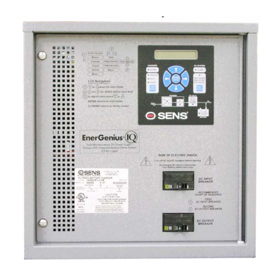
SENS IQ Technical Manual FRONT PANEL CONTROLS Front Panel User Interface Description The front panel User Interface provides visual indication of DC output voltage and current, as well as the charging mode (FLOAT or EQUALIZE), equalize time elapsed, and status of all alarms. The front panel User Interface is shown below in FIG 4. -
Page 15: Commission Batteries
SENS IQ Technical Manual 7. BATTERY CHECK BUTTON AND STATUS LED - Press BATT CHCK to activate the Battery Check feature (see Section 8. 4 ). The status LED displays test progress and outcome. Amber indicates the test is in progress. Green indi- cates the Battery Check passed successfully. -
Page 16: 8.3.2.2 Demand Based Automatic Equalize Mode
SENS IQ Technical Manual the equalize voltage until the equalize time period (see Section 8.3) has expired, or the FLOAT setting is selected manually with the front panel CHARGE MODE SELECT button. If the charger is switched from EQUALIZE to FLOAT, then back to EQUALIZE, this resets the equalize time period. -
Page 17: 8.3.2.3 Periodic Automatic Equalize Mode
SENS IQ Technical Manual 8.3.2.3 Periodic Automatic Equalize Mode Press the front panel CHARGE MODE SELECT button to engage AUTO mode and see Section 8.5.2 to configure and activate Periodic EQUALIZE. The Periodic Automatic EQUALIZE mode provides an automatic EQUALIZE cycle on a regular interval configured by the user . When in EQUALIZE mode, the charger will revert to FLOAT mode when the equalize time period has expired. -
Page 18: User Interface Display Menus
SENS IQ Technical Manual User Interface Display Menus 8.6.1 User Interface Display Menu Instructions The IQ charger User Interface uses an X-Y navigation system with main fields up and down, and details within each field left and right (see FIG 6). Press the up and down arrow keys to scroll through main menu options. - Page 19 SENS IQ Technical Manual Main Menus Configurable/Viewable Parameter Descriptions/Definitions (Press up and down Parameters arrows to scroll (Press left and right arrows through Main Menu to scroll through choices Options) within each Menu Option) EQUALIZE Adjust the amount of time from 1 to 255 hours that the charger will be in EQUAL- VALUES IZE mode.
- Page 20 SENS IQ Technical Manual Main Menus Configurable/Viewable Parameter Descriptions/Definitions (Press up and down Parameters arrows to scroll (Press left and right arrows through Main Menu to scroll through choices Options) within each Menu Option) Adjust VpC setpoint to trigger Over Voltage Shutdown alarm. Adjustable from...
-
Page 21: Figure 7: Two Temperature Compensation Curve Examples
Second line reports number of non-empty pages that fail (available with version 3.00 or CRC check. Contact SENS Customer Service if errors exist. later firmware) Press UP arrow to set alarm relays to FAIL, LCD black, multi-color LEDs Relay &... -
Page 22: Adjustment Limits/Voltage Setting Interlocks
SENS IQ Technical Manual 8.6.3 Adjustment Limits/Voltage Setting Interlocks Figure 8: Charger Adjustment Limits for Flooded and VRLA Batteries Figure 9: Charger Adjustment Limits for Nickel-Cadmium Batteries Service Hotline: 1.800.742.2326 1.303.678.7500... -
Page 23: User Interface Mode-Unlock/Lock Jumper
SENS IQ Technical Manual User Interface Mode—Unlock/Lock Jumper Three User Interface Modes are available to ensure that charger parameters are not mistakenly changed and are only configurable when desired. Move the unlock/lock jumper to the unlock position to change User Interface Mode. -
Page 24: Alarms
SENS IQ Technical Manual ALARMS Summary Alarm Contact The charger provides a ‘SUMMARY’ form C relay, which changes state if any of several alarm conditions exist , as described in Section 9.3 . The relay changes state a user-settable time period, ranging from 5 to 50 seconds (see Section 8.6.2), after the onset of a fault and is located on the Control Printed Circuit Board... - Page 25 SENS IQ Technical Manual against nuisance trips. If over voltage is caused by an external source the charger will not execute an Over Volt- age Shutdown. If an over voltage condition persists for 30 seconds, and the charger itself is the cause, the charger will latch off.
-
Page 26: Black Box Data Recorder
Contact SENS (1-800-742-2326 or www.sens-usa.com) for assistance downloading and analyzing history data. User must document date and time Black Box Data Recorder is removed from charger to maintain accurate date and time for logged data. -
Page 27: Typical Settings
SENS IQ Technical Manual TYPICAL SETTINGS 11.1 Typical Battery Settings Factory settings for float and equalize voltages and alarm settings for the most common battery configurations are shown for reference in Tables 7, 8 and 9. See the test data sheet provided with your charger for actual values. -
Page 28: Maintenance And Troubleshooting
SENS IQ Technical Manual Table 9: Non-temperature compensated factory charger output DC voltage and alarm threshold settings for NiCd batteries Setting Volts Cells Cells Cells Cells Cells Cells Cells Cells Cells Cells Cell 1.43 12.87 14.30 27.16 28.60 52.90 54.30 131.5... -
Page 29: Figure 12: Troubleshooting Chart For Repeated Ac Breaker Trip
SENS IQ Technical Manual Figure 12: Troubleshooting chart for repeated AC breaker trip START SELECT MODELS: PROPERLY 3-WAY INPUT BREAKER CONFIGURE SELECTION JUMPER STILL TRIPS? SELECTION JUMPER PROPERLY CONFIGURED? AC VOLTS AND CORRECT AC MAINS FREQ CORRECT? BREAKER SUPPLY PROBLEM OR ORDER... -
Page 30: Figure 13: Troubleshooting Flowchart For Ac Fail Alarm Indication
SENS IQ Technical Manual Figure 13: Troubleshooting flowchart for AC FAIL alarm indication START SELECT MODELS: PROPERLY 3-WAY INPUT ALARM STILL CONFIGURE SELECTION JUMPER PRESENT? SELECTION JUMPER PROPERLY CONFIGURED? CORRECT AC MAINS SUPPLY AC VOLTS AND PROBLEM OR ORDER FREQ CORRECT? -
Page 31: Figure 14: Troubleshooting Flowchart For Charge Fail Alarm
SENS IQ Technical Manual Figure 14: Troubleshooting flowchart for CHARGE FAIL alarm START CLOSE OUTPUT BREAKER OUTPUT BREAKER OPEN? ALARM STILL PRESENT? CONNECTORS FIRMLY CONNECTIONS SEATED? ALARM STILL PRESENT? CHECK POWER SEMICONDUCTORS SEMICONDUCTORS REPLACE OPERATING SEMICONDUCTORS PROPERLY? ALARM STILL PRESENT? -
Page 32: Figure 15: Troubleshooting Flowchart For Dc Output Breaker Trip
SENS IQ Technical Manual Figure 15: Troubleshooting flowchart for DC output breaker trip START DOES CHARGER CHANGE CHARGER TO MATCH OUTPUT MATCH BATTERY VOLTAGE BATTERY VOLTAGE? BREAKER STILL TRIPS? CHECK SEMICONDUCTORS AND OUTPUT CAPS SEMICONDUCTORS REPLACE AND OUTPUT CAPS SEMICONDUCTORS/OUTPUT... - Page 33 SENS IQ Technical Manual Figure 16: Troubleshooting flowchart for HIGH DC or OVER VOLTAGE SHUTDOWN alarms START LOAD BATTERY TO BLEED OFF SURFACE CHARGE, CLOSE DC OUTPUT BREAKER OPEN AC INPUT BREAKER, OPEN DC OUTPUT BREAKER, WAIT 30 SEC, CLOSE AC INPUT...
-
Page 34: Figure 17: Troubleshooting Flowchart For Low Dc Alarm
SENS IQ Technical Manual Figure 17: Troubleshooting flowchart for LOW DC alarm START AC INPUT VOLTS CORRECT INPUT SOURCE AND FREQ PROBLEM CORRECT? ALARM STILL PRESENT? OPEN DC OUTPUT BREAKER, MEASURE DC VOLTAGE ON CHARGER SIDE OF BREAKER FLOAT AND... -
Page 35: Figure 18: Troubleshooting Flowchart For No Output
SENS IQ Technical Manual Figure 18: Troubleshooting flowchart for no output START OVER VOLTAGE OPEN AC AND DC BREAKERS, SHUTDOWN WAIT 30 SEC, CLOSE AC ALARM ACTIVE? BREAKER DC OUTPUT ON CHARGER SIDE OF OUTPUT BREAKER CORRECT? CHECK POWER SEMICONDUCTORS... -
Page 36: Figure 19: Troubleshooting Flowchart For Ground Fault Alarm
SENS IQ Technical Manual Figure 19: Troubleshooting flowchart for GROUND FAULT alarm START REMOVE LEAKAGE CURRENT TWO CHARGERS OR LOWER/DISABLE GROUND CONNECTED IN FAULT SENSITIVITY PARALLEL? ALARM STILL PRESENT? GROUND FAULT LIKELY FALSE. COMMSGENIUS CONNECT COMMSGENIUS LOAD-SHARE LOAD-SHARE CABLE TO ENSURE CABLE CON- PROPER PARALLEL OPERATION. - Page 42 Certificate Number: 13-HS1014518-2-PDA 20/MAY/2014 Confirmation of Product Type Approval Please refer to the "Service Restrictions" shown below to determine if Unit Certification is required for this product. This certificate reflects the information on the product in the ABS Records as of the date and time the certificate is printed.
- Page 43 Supporting Data: Product Specification PRODSPEC- 135, Rev. L, Sync with: Eng. Rev. C, DCN 106304, EnerGenius I/Q Utility Grade Charger and Battery Check System, dated 16 JUL 2013, 20 Pages; SENS IPX2 Q1 and Q2 Enclosure Drip Test; Cascade TEK Test Report Number: CTC C662 Dated May 22, 2013;...
- Page 44 Return Material Authorization (RMA) number provided SENS. If, in SENS’ opinion, the problem can be rectified in the field, SENS may elect to ship replacement parts for customer installation instead of having the product returned to the factory.
Need help?
Do you have a question about the Q012-012 and is the answer not in the manual?
Questions and answers