Table of Contents
Advertisement
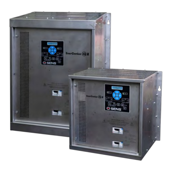
Automatic Battery Charger & DC Supply
Installation & Operation Manual
SENS Part Number:
Document Revision:
DCN Number:
Date:
MADE IN U.S.A
PATENTED US 9,270,140; 9,385,556; 9,413,186; 9,509,164;
9,466,995; 9,948,125
Installation or service questions?
Call SENS between 8 a.m. and 5 p.m. (Mountain Time),
Monday through Friday or visit our website.
Copyright © Stored Energy Systems LLC 2021
The SENS name / logo, EnerGenius, HELIX, and Dynamic Boost are trademarks of Stored Energy Systems LLC
12 to 240 Volts Nominal, 6 to 150 Amps
101340-1
A
108031
May 18, 2021
1
SENS EnerGenius IQ2 Technical Manual
1840 Industrial Circle
Longmont, CO 80501
Phone: 303.678.7500
800.742.2326
Fax:
303.678.7504
Email:
service@sens-usa.com
Web:
www.sens-usa.com
Advertisement
Table of Contents

Related Manuals for Sens EnerGenius IQ2


Summary of Contents for Sens EnerGenius IQ2
- Page 1 Call SENS between 8 a.m. and 5 p.m. (Mountain Time), Monday through Friday or visit our website. Copyright © Stored Energy Systems LLC 2021 The SENS name / logo, EnerGenius, HELIX, and Dynamic Boost are trademarks of Stored Energy Systems LLC...
-
Page 2: Table Of Contents
Restore Factory Defaults ........................33 9.9. Keypad Operation ..........................33 9.9.3. Menu Options ............................ 34 9.10. Configuration with SENS Setup Utility ....................39 9.11. Temperature Compensation ....................... 39 9.12. Load Share Charger Operation ......................40 MODBUS COMMUNICATIONS ........................40 10.1. - Page 3 SENS EnerGenius IQ2 Technical Manual 10.9. Accessory System Alarms Bit Definition ....................45 10.10. Accessory Assigned Channel Alarms Bit Definition ................45 10.11. Writable Control Flags (Coils) ......................45 10.12. Legacy IQ Modbus ..........................46 MAINTENANCE AND TROUBLESHOOTING ....................52...
-
Page 4: Important Safety Instructions For Installer And Operator
SENS EnerGenius IQ2 Technical Manual IMPORTANT SAFETY INSTRUCTIONS FOR INSTALLER AND OPERATOR 1.1. SAVE THESE INSTRUCTIONS – This manual contains important safety and operating instructions for ® EnerGenius IQ2 battery chargers. 1.2. Before using battery charger, read all instructions and cautionary markings on battery charger, battery, and product using battery. - Page 5 1.11.8. When charging batteries, charge LEAD-ACID or LIQUID ELECTROLYTE NICKEL-CADMIUM batteries only. Consult SENS before using with any other type of battery - other batteries may burst and cause injuries to persons and damage to property.
-
Page 6: Quick Installation Guide
A. Read all cautionary warnings in section 1. B. Remove the charger from the packaging and inspect for damage. See section for information on moving and lifting the charger. Notify SENS immediately (1-800-742-2326) if damage from shipping is evident. C. See section for mounting options. -
Page 7: Performance Specifications
The digital load sharing cable should never be connected when two chargers are each connected to different batteries. PERFORMANCE SPECIFICATIONS See IQ2 Product Data Sheet and Product Specification on SENS website (www.sens-usa.com) for detailed performance specifications. -
Page 8: Model Number Breakout
SENS EnerGenius IQ2 Technical Manual MODEL NUMBER BREAKOUT Field Parameter Code Value Product Family Q EnerGenius IQ 012 12 volts 024 24 volts Output Voltage 048 48 volts 120 120 volts 240 240 volts 006 6 amps 012 12 amps... -
Page 9: Mechanical Installation
Refer to the label on the inside of the door for factory configured output and alarm relay assignments. The charger may be reconfigured using the front panel keypad or by software programming using the SENS Setup Utility. See drawings at back of manual for quick reference installation information. Diagrams reflect charger setup for a typical installation only. - Page 10 SENS EnerGenius IQ2 Technical Manual circuit must be connected to the charger-grounding terminal. Input (AC line) wiring must be kept at least 1/4" (6.3 mm) away from all output, alarm, data interface wiring, and from other uninsulated electrical parts not connected to the input conductor.
-
Page 11: Dc Output Connections
SENS EnerGenius IQ2 Technical Manual NOTE: Breakers designated as “10, 15” indicate a 10 Amp breaker for input code T and a 15 Amp breaker for input code P. Table 2: AC Input Wire Gauge Ratings Rated Charger Input Wire Gauge ≤... -
Page 12: Alarm Wiring
(see Figure 2). See Table 4 for assignment details. Alarm relay assignments are custom configurable using the SENS Setup Utility. Conduit knockouts are provided for alarm wires. Connect alarm wiring to alarm terminal blocks (see drawings at back of manual). - Page 13 SENS EnerGenius IQ2 Technical Manual Figure 1 – Alarm Relays (case size Q2 with optional alarm relay and communications protocol circuit boards shown) Control circuit board summary Optional alarm relay alarm relay circuit board Optional communications protocol circuit board relays Figure 2 –...
-
Page 14: Operating Chargers In Parallel
• Chargers configured at the factory for genset applications (code GEN) include relay 1-5 assignments: Summary, AC Fail + Charger Fail, Low Crank, High DC, Low DC. Relays 6-8 assignable using SENS Setup Utility. • Chargers configured at the factory for marine applications (code MAR) include relay 1-5 assignments: Summary, AC Fail + Charger Fail, Ground Fault, High DC, Low DC. - Page 15 SENS EnerGenius IQ2 Technical Manual block may be connected to the RJ-45 connector and is available to order separately (SENS p/n 208026, see Figure 4). Figure 3 – CANbus and RS-485 RJ-45 Connections (case size Q2 with optional alarm relay and communications protocol circuit boards shown)
-
Page 16: Ethernet-Optional
(see Figure 6 and drawings at back of manual). Connect Cat5 or better ethernet cable. This provides a 10/100 ethernet connection. Ethernet communication includes ethernet connectivity to the charger for monitoring and configuration via the SENS Setup Utility and/or communications protocols such as Modbus TCP/IP (optional) and DNP3 (optional). -
Page 17: Sensbus Connection-Optional
(case size Q2 with optional alarm relay and communications protocol circuit boards shown) 6.6.1. Configure TCP/IP Address Configure TCP/IP settings using the SENS Setup Utility or the keypad. To adjust settings using the keypad, ensure the access level is set to allow adjustments. Set the IP address as desired. It may take up to 10 seconds for the network setting changes to apply. - Page 18 Leave a factory installed 120-ohm terminator in a SENSbus port on each charger to ensure a terminator is located at both ends of the communications bus. The only optional hardware required is a Cat5 or better RJ-45 network cable available either from SENS or local computer supply.
-
Page 19: Remote Temperature Sensor Connection-Optional
It is most critical in applications where battery and charger are located in different ambient conditions. Temperature compensation is disabled by setting the temperature compensation slope to zero using the keypad or SENS Setup Utility. See section 9.11 for further information regarding temperature compensation. -
Page 20: Power On/Power Off Procedures
Refer to the label on the charger front door for factory configured output voltage, battery type and configuration code (see Figure 2). Review and adjust charger configuration using the front panel keypad or the SENS Setup Utility if factory configured settings require modification. See section 9.9.3 additional details on keypad navigation. -
Page 21: Verify Charger Output
SENS EnerGenius IQ2 Technical Manual 7.2.3.3. MARINE (MAR) This configuration code is intended for standard marine applications. 7.2.3.4. Power Supply (PSP) This configuration code is intended for standard power supply applications where a storage battery is not connected. 7.3. Verify Charger Output Connect a portable voltmeter to the line side of the charger DC output circuit breaker. -
Page 22: Alarms, Leds And Display
SENS EnerGenius IQ2 Technical Manual ALARMS, LEDS AND DISPLAY 8.1. Front Panel User Interface The front panel user interface provides information about input, output, charging status and alarms and allows configuration using the keypad. The front panel user interface is shown below in Figure 9. Press the Enter to save a setting or move backward within the user interface menus (see section 9.9.3... -
Page 23: Mimic Panel Leds
SENS EnerGenius IQ2 Technical Manual Table 6 – LED Definitions AC LED DC LED Meaning AC and DC not applied or charger failed or alarm/communications circuit board cannot communicate with main circuit board SOLID GREEN SOLID GREEN AC good, DC good, in Float Mode... -
Page 24: Individual Alarm Relay Contacts
All alarm messages displayed on the front panel LCD are latching. Alarm relay configurations created using the SENS Setup Utility may be configured as latching if desired. Once an alarm condition no longer exists, the alarm message will no longer display in the main/home screen but will remain under the “Latched Alarms”... - Page 25 Voltage factory alarm setpoint (see Table 8) or the configured level if setpoint is adjusted using keypad or SENS Setup Utility. The BATTERY DISCHARGING alarm is the first to trigger of three low output voltage alarms and is followed by LOW DC and then END OF DISCHARGE. Alarm setpoint must be set higher than LOW DC and END OF DISCHARGE alarms.
- Page 26 Indicates battery has discharged and DC output voltage is below Low DC Voltage factory alarm setpoint (see Table 9) or the configured level if setpoint is adjusted using keypad or SENS Setup Utility. Alarm setpoint must be set lower than BATTERY DISCHARGING and higher than END OF DISCHARGE alarms.
- Page 27 Over Voltage Shutdown factory alarm setpoint (see Table 11) or the configured level if setpoint is adjusted using keypad or SENS Setup Utility. The charger disables itself whenever excessive output voltage occurs while the charger is delivering current. The overvoltage shutdown system is protected against nuisance trips and will not execute if the high voltage condition is caused by an external source including a parallel connected charger of any type.
- Page 28 SENS EnerGenius IQ2 Technical Manual 8.7.11. SENSbus Inactive Indicates the charger is not communicating on SENSbus either when load sharing and/or remote accessories are connected. Activates flashing long then 2x short yellow AC and DC LEDs. When this alarm is assigned to a relay contact SENSBUS INACTIVE will cause the assigned relay to change to the Failed state after the time delay.
- Page 29 Indicates battery voltage is below the factory Startup Voltage setpoint or the configured level if setpoint is adjusted using keypad or SENS Setup Utility. When this alarm is assigned to a relay contact DC BELOW STARTUP VOLTAGE will cause the assigned relay to change to the Failed state after the time delay.
- Page 30 SENS EnerGenius IQ2 Technical Manual state after the time delay. 8.7.29. AC Voltage Low Indicates AC Voltage has gone below AC Min Voltage alarm setpoint. Activates solid yellow AC LED. When this alarm is assigned to a relay contact AC VOLTAGE LOW will cause the assigned relay to change to the Failed state after the time delay.
-
Page 31: Operation
SENS EnerGenius IQ2 Technical Manual OPERATION 9.1. Charging Algorithms The charger uses charging algorithms appropriate for different battery types. The charging algorithm for each battery type includes various combinations of Float mode, Dynamic Boost™ mode, and HELIX mode, as described in Table 12. See following sections for descriptions of each charging mode. -
Page 32: Helix Mode
Dynamic Boost can be enabled or disabled by the user at any time. Configure the charger appropriately using the keypad or SENS Setup Utility. Use of the optional remote temperature compensation sensor is highly recommended to maximize charging performance and optimize battery life. -
Page 33: Commissioning Batteries
AC and DC power to reset the charger and resume charging. This safety feature can be temporarily defeated from the keypad or the SENS Setup Utility in order to charge/commission a zero-volt or fully discharged battery. Use the keypad or SENS Setup Utility to set the desired minimum startup voltage level and initiate a forced startup. -
Page 34: Menu Options
SENS EnerGenius IQ2 Technical Manual security code to a unique value using the front panel keypad. Contact SENS Customer Service if a custom password is lost or forgotten (800-742-2326 or www.sens-usa.com). 9.9.2. Menu Navigation Use the keypad to scroll through settings to view and adjust. The keypad provides X-Y navigation with main fields up and down and details within each field left and right (see Table 15). - Page 35 SENS EnerGenius IQ2 Technical Manual Adjust temperature compensation slope from 0 Temp. comp./°C to -0.30%V/°C Adjust output Boost voltage from, must be same Boost Voltage or greater than Float setting, must not be greater than 166% of Float setting Adjust amount of time from 0 to 5 minutes to...
- Page 36 SENS EnerGenius IQ2 Technical Manual Adjust setpoint to trigger Battery End-of- End Discharge Discharge alarm, must be less than Low DC setting Adjust setpoint to trigger Low DC voltage alarm, Low DC Voltage must be greater than End Discharge setting and...
- Page 37 SENS EnerGenius IQ2 Technical Manual Set to 1 for single-phase or 3 for three-phase Number of Phases input voltage Basic Set nominal input voltage for charger model. Settings Nominal Volts AC Must match hardware jumper/terminal block on inside of charger when jumper exists.
- Page 38 SENS EnerGenius IQ2 Technical Manual Press UP arrow to set all alarm relays and DOWN Relay Test arrow to clear all relays Press UP arrow to set all LCD segments black and Display Test DOWN arrow to clear all LCD segments...
-
Page 39: Configuration With Sens Setup Utility
Communication between a computer and the charger using the SENS Setup Utility requires connection of a Cat5 minimum RJ45 cable between the ethernet port on the charger and the ethernet port on the computer (see section 6.6). Connect using the “SENSnet”... -
Page 40: Load Share Charger Operation
Serial Modbus communications over RS-485 using RTU mode is optional. Modbus communications settings may be configured using the keypad or SENS Setup Utility prior to executing communications. Configure Modbus slave address, baud rate, parity and enable/disable Modbus write access as desired. -
Page 41: Modbus Holding Registers
SENS EnerGenius IQ2 Technical Manual Data Bits Parity Even Stop Bits Slave Address 10.3. Modbus Holding Registers EnerGenius IQ products provide an extensive array of Modbus registers. The following are common registers that are applicable to most applications. The entire list of Modbus registers is available from sens-usa.com/support/download-center/. -
Page 42: Basic Charging Alarms Bit Definition
SENS EnerGenius IQ2 Technical Manual Power currently being supplied by 0x0D8 0x0D9 Unit Power 32768 the unit 0x0DA 0x0DB Unit Float Voltage Float Voltage Setting of the unit V/cell 32768 0x0DC 0x0DD Unit Boost Voltage Boost Voltage Setting of the unit... -
Page 43: Charging Status Bit Definition
SENS EnerGenius IQ2 Technical Manual Ground Fault Ground fault current to the positive output terminal is above the 0x0D Positive Ground Fault Trip sensitivity setpoint. 0x0E Low Current Output Current is under the Low Current Alarm setpoint. Load Share Modules or chargers connected for load sharing are not sharing the... -
Page 44: Charging Alarms Extended Bit Definition
SENS EnerGenius IQ2 Technical Manual 10.6. Charging Alarms Extended Bit Definition Bit Address Name Description Decimal Module has experienced a thermal roll back which can 0x00 Check Filter be caused by a clogged input air filter. Module has faulted because it over-heated and thermal... -
Page 45: Accessory System Alarms Bit Definition
SENS EnerGenius IQ2 Technical Manual 10.9. Accessory System Alarms Bit Definition Bit Address Name Description Decimal Invalid System Configuration of system is conflicted. Charger will continue to operate 0x00 Config but may not be fully functional until the issue is resolved. -
Page 46: Legacy Iq Modbus
SENS EnerGenius IQ2 Technical Manual Address Description Details Decimal 0x015 Not applicable Not applicable 0x016 Force DC Startup ON to start, OFF to stop 0x017 Reset Latched Alarms ON to reset alarm, OFF is no-op 10.12. Legacy IQ Modbus Use the below tables for Modbus information using legacy IQ registers. Legacy IQ Modbus would be used in systems that were set up to poll an IQ built before May 2021. - Page 47 SENS EnerGenius IQ2 Technical Manual Enumerated: 0 = NICD, 1 = VRLA, 12311 0x3017 12311 0x3017 Cell Chemistry Enum 2 = FLA 12312 0x3018 12312 0x3018 Auto-Boost Time Limit Automatic boost time-out 12313 0x3019 12313 0x3019 Ground Alarm Current Ground fault trip current...
- Page 48 SENS EnerGenius IQ2 Technical Manual 10.12.2. Legacy IQ Modbus Input Registers Scale Address High Address Low Name Description Units Factor Deci- Deci- Minutes remaining for this equalize 8192 0x2000 8192 0x2000 Equalize Timer cycle Seconds remaining for this battery 8193...
- Page 49 SENS EnerGenius IQ2 Technical Manual 8706 0x2202 8706 0x2202 Charger2 Output Voltage 1351 = 13.51Vdc 8707 0x2203 8707 0x2203 Charger2 Output Current 4950 = 49.50Adc Charger2 Percent Input 8708 0x2204 8708 0x2204 101 = 101% of rated input voltage Voltage Charger2 Internal Temp.
- Page 50 SENS EnerGenius IQ2 Technical Manual Address Description Details Decimal 0x010E Charger1 Negative Ground Negative ground fault 0x010F Charger1 Battery Discharge Voltage below discharge threshold Obsolete - Charger1 Redundancy 0x0110 Obsolete - Charger will not support system load Check True = an overvolt condition has caused charger to shut 0x0111 Charger1 OverVoltage Shutdown down.
- Page 51 SENS EnerGenius IQ2 Technical Manual Address Description Details Decimal Obsolete - Periodic Obsolete - Repeat both redundancy tests at scheduled 4098 0x1002 Redundancy Test intervals Enable battery voltage temperature compensation - READ 4099 0x1003 Temperature Compensation ONLY 4100 0x1004 Timed Equalize...
-
Page 52: Maintenance And Troubleshooting
SENS EnerGenius IQ2 Technical Manual 11 MAINTENANCE AND TROUBLESHOOTING WARNING: CHARGER CONTROL CIRCUITS ARE AT BATTERY POTENTIAL AND CAN BE HAZARDOUS IF TOUCHED. ONLY INSULATED TOOLS SHOULD BE USED WHILE WORKING ON A CHARGER THAT IS POWERED UP. AVOID TOUCHING ANY CIRCUIT OR ANY BARE METAL. - Page 53 SENS EnerGenius IQ2 Technical Manual Figure 11: Troubleshooting chart for repeated AC breaker trip START SELECT MODELS: 2-WAY or BREAKER PROPERLY 3-WAY INPUT STILL TRIPS? CONFIGURE SELECTION JUMPER SELECTION JUMPER PROPERLY CONFIGURED? AC VOLTS AND FREQ CORRECT AC MAINS SUPPLY PROBLEM OR ORDER...
- Page 54 SENS EnerGenius IQ2 Technical Manual Figure 12: Troubleshooting flowchart for AC FAIL alarm indication START SELECT MODELS: 2-WAY or PROPERLY 3-WAY INPUT ALARM STILL CONFIGURE SELECTION JUMPER PRESENT? SELECTION JUMPER PROPERLY CONFIGURED? CORRECT AC MAINS SUPPLY AC VOLTS AND FREQ...
- Page 55 SENS EnerGenius IQ2 Technical Manual Figure 13: Troubleshooting flowchart for CHARGE FAIL alarm START CLOSE OUTPUT BREAKER OUTPUT BREAKER OPEN? ALARM STILL PRESENT? CONNECTORS CONNECTIONS FIRMLY SEATED? ALARM STILL PRESENT? CHECK POWER SEMICONDUCTORS SEMICONDUCTORS REPLACE OPERATING PROPERLY? SEMICONDUCTORS ALARM STILL...
- Page 56 SENS EnerGenius IQ2 Technical Manual Figure 14: Troubleshooting flowchart for DC output breaker trip START DOES CHARGER CHANGE CHARGER TO MATCH OUTPUT MATCH BATTERY VOLTAGE BATTERY VOLTAGE? BREAKER STILL TRIPS? CHECK SEMICONDUCTORS AND OUTPUT CAPS SEMICONDUCTORS AND REPLACE OUTPUT CAPS...
- Page 57 SENS EnerGenius IQ2 Technical Manual Figure 15: Troubleshooting flowchart for HIGH DC or OVER VOLTAGE SHUTDOWN alarms START LOAD BATTERY TO BLEED OFF SURFACE CHARGE, CLOSE DC OUTPUT BREAKER OPEN AC INPUT BREAKER, OPEN DC OUTPUT BREAKER, WAIT 30 SEC,...
- Page 58 SENS EnerGenius IQ2 Technical Manual Figure 16: Troubleshooting flowchart for LOW DC alarm START AC INPUT VOLTS AND CORRECT INPUT SOURCE FREQ CORRECT? PROBLEM ALARM STILL PRESENT? OPEN DC OUTPUT BREAKER, MEASURE DC VOLTAGE ON CHARGER SIDE OF BREAKER FLOAT AND EQUALIZE...
- Page 59 SENS EnerGenius IQ2 Technical Manual Figure 17: Troubleshooting flowchart for no output START OVER VOLTAGE OPEN AC AND DC BREAKERS, WAIT SHUTDOWN ALARM 30 SEC, CLOSE AC BREAKER ACTIVE? DC OUTPUT ON CHARGER SIDE OF OUTPUT BREAKER CORRECT? CHECK POWER...
- Page 60 SENS EnerGenius IQ2 Technical Manual Figure 18: Troubleshooting flowchart for GROUND FAULT alarm START REMOVE LEAKAGE CURRENT OR TWO CHARGERS LOWER/DISABLE GROUND FAULT CONNECTED IN SENSITIVITY PARALLEL? ALARM STILL PRESENT? GROUND FAULT LIKELY FALSE. LOAD-SHARE CONNECT LOAD-SHARE CABLE TO CABLE...
-
Page 61: Glossary
Equalize charging is employed to improve the performance and life of an already charged battery that is primarily charged using Float voltage. SENS’ convention is to employ the term “Boost” to mean both this cell equalization function and the fast battery recharge function. - Page 73 Certificate Number: 18-HS1725925-PDA 27/MAR/2018 Confirmation of Product Type Approval Please refer to the "Service Restrictions" shown below to determine if Unit Certification is required for this product. This certificate reflects the information on the product in the ABS Records as of the date and time the certificate is printed.
- Page 74 07-14-2017 Supporting Documentation listed in ABS Task T1182566: Product Specification PRODSPEC- 135, EnerGenius IQ detailed product specification, Rev. L SENS IPX2 Q1 and Q2 Enclosure Drip Test; Cascade TEK Test Report Number: CTC C662 Dated May 22, 2013; Term of Validity:...
- Page 75 Directives(s) and Standard(s). ________________________________________ _April 28, 2020_______ Sam Coleman Date Compliance Manager Stored Energy Systems, LLC STORED ENERGY SYSTEMS, LLC1840 INDUSTRIAL CIRCLE, LONGMONT, COLORADO 80501 FAX 303.678.7504 303.678.7500 www.sens-usa.com email: info@sens-usa.com FORM-246 REV F DATE ISSUED: 4/28/2020...
- Page 76 Return Material Authorization (RMA) number provided by SENS. If, in SENS’ opinion, the problem can be rectified in the field, SENS may elect to ship replacement parts for customer installation instead of having the product returned to the factory.
Need help?
Do you have a question about the EnerGenius IQ2 and is the answer not in the manual?
Questions and answers