Table of Contents
Advertisement
Quick Links
Installation & Operation Manual
SENS Part Number:
Document Revision:
DCN Number:
Date:
PATENTED US 9,270,140; 9,385,556; 9,413,186; 9,509,164;
9,466,995; 9,948,125; 10,575,433
Installation or service questions?
Call SENS between 8 a.m. and 5 p.m. (Mountain Time),
Monday through Friday, or visit our website.
Copyright © Stored Energy Systems LLC 2020
The SENS name / logo, EnerGenius, HELIX, and Dynamic Boost are trademarks of Stored Energy Systems LLC
COMPACT
Automatic Battery Charger/Power Supply
101334
B
107947
April 27, 2021
SENS EnerGenius® DC Compact Technical Manual
1
1840 Industrial Circle
Longmont, CO 80501
Phone: 303.678.7500
800.742.2326
Fax:
303.678.7504
Email:
service@sens-usa.com
Web:
www.sens-usa.com
Advertisement
Table of Contents
Troubleshooting

Related Manuals for Sens EnerGenius DC COMPACT


Summary of Contents for Sens EnerGenius DC COMPACT
- Page 1 Call SENS between 8 a.m. and 5 p.m. (Mountain Time), Web: www.sens-usa.com Monday through Friday, or visit our website. Copyright © Stored Energy Systems LLC 2020 The SENS name / logo, EnerGenius, HELIX, and Dynamic Boost are trademarks of Stored Energy Systems LLC...
-
Page 2: Table Of Contents
Battery Check ............................. 35 9.8. Restore Factory Defaults ........................35 9.9. Keypad Operation ..........................35 9.10. Configuration and Monitoring with SENS Setup Utility ................ 40 9.11. Temperature Compensation ....................... 40 9.12. Load Share Charger Operation ......................41 9.13. Remote Alarm/Communications Panel Accessory ................41 9.14. - Page 3 SENS EnerGenius® DC Compact Technical Manual 11.4. Basic Charging Alarms Bit Definition ....................45 11.5. Charging Status Bit Definition ......................46 11.6. Charging Alarms Extended Bit Definition ..................... 46 11.7. Charging AC Alarms Bit Definition ....................... 47 11.8. Accessory Channel Alarms Bit Definition ..................... 47 11.9.
-
Page 4: Important Safety Instructions For Installer And Operator
SENS EnerGenius® DC Compact Technical Manual IMPORTANT SAFETY INSTRUCTIONS FOR INSTALLER AND OPERATOR 1.1. SAVE THESE INSTRUCTIONS – This manual contains important safety and operating instructions for EnerGenius DC compact battery chargers. 1.2. Before using battery charger, read all instructions and cautionary markings on battery charger, battery, and product using battery. - Page 5 1.10.8. When charging batteries, charge LEAD-ACID or LIQUID ELECTROLYTE NICKEL-CADMIUM batteries only. Consult SENS before using with any other type of battery - other batteries may burst and cause injuries to persons and damage to property. NEVER charge a frozen battery.
-
Page 6: Model Number Breakout
SENS EnerGenius® DC Compact Technical Manual MODEL NUMBER BREAKOUT Parameter Code Value Product Family EnerGenius DC Enclosure Type Compact AC Input Voltage Three Phase - 480VAC 120 VDC DC Output Voltage 240 VDC 120 VDC 240VDC ✓ ✓ ✓ Output Current ✓... -
Page 7: Performance Specifications
SENS EnerGenius® DC Compact Technical Manual PERFORMANCE SPECIFICATIONS EnerGenius® DC is a high power industrial/utility class 3-phase switchmode battery charger/power supply, specially hardened for use in harsh industrial environments. Advanced technology switch mode power conversion is significantly smaller & lighter than conventional line frequency (e.g. SCR) power conversion and, even without a battery connected, delivers lower output ripple and much faster dynamic response. - Page 8 Local computer Change all parameters, troubleshoot, create/save configuration files for quick download to chargers using network connection and SENS Setup Utility software available at www.sens-usa.com Status Reporting LEDs Two multi-color front panel status LEDs Metering AC/DC Voltmeter accurate to ±1%;...
- Page 9 SENS EnerGenius® DC Compact Technical Manual Alarm Inputs Two optional input contacts (via optional battery monitor) to monitor status of, and modify charger operation based on, external devices such as battery room fan or hydrogen monitor. Alarm Form C contacts Five Form C contacts, rated 30V, 2A resistive, assignable.
-
Page 10: System Overview
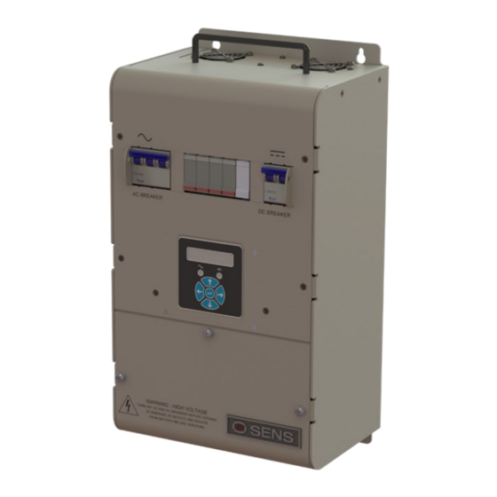
AC and alarms/comms Network/Alarm Modbus: RJ-45 or terminal blocks 28 to 16 AWG. Form C connections alarms: 28 to 16 AWG. Power connections AC/DC terminal blocks: 14 – 3AWG SYSTEM OVERVIEW 4.1. Physical Overview Figure 1 – EnerGenius DC Compact Overview... -
Page 11: Functional Overview
Some of the available configuration options may not be applicable to a given installation. Adjustments to settings can be made via the front panel keypad or the SENS Setup Utility software via ethernet connection of the EnerGenius DC Compact unit to a computer. -
Page 12: Mounting Instructions
SENS EnerGenius® DC Compact Technical Manual MOUNTING INSTRUCTIONS INSTALLATION OF THE UNIT MUST COMPLY WITH LOCAL ELECTRICAL CODES AND OTHER APPLICABLE INSTALLATION CODES AND BE MADE ACCORDING TO THE INSTALLATION INSTRUCTIONS AND ALL APPLICABLE SAFETY REGULATIONS. Printed circuit boards contain static sensitive components. Damage can occur even when static levels are too low to produce a noticeable discharge shock. -
Page 13: Setup And Wiring
Refer to the label on the inside lower cover for factory configured output and alarm relay assignments. The charger can be reconfigured using the front panel keypad or by software programming using the SENS Setup Utility that runs on a Windows PC. - Page 14 SENS EnerGenius® DC Compact Technical Manual Table 2 – DC Output Cable Size Maximum Charger to Charger Rated Wire Size Resistance per Battery Distance (Ft.) Output Current Foot (mΩ/Ft.) (Amps) 120V 240V 0.63 1270 1000 2000 0.63 1000 0.63 NEC - not allowed NEC - not allowed 0.63...
-
Page 15: Grounding Instructions And Connection
SENS EnerGenius® DC Compact Technical Manual 6.2. Grounding Instructions and Connection 6.2.1. Charger must be grounded to reduce risk of electric shock. The charger must be connected to a grounded, metal, permanent wiring system, or an equipment-grounding conductor (earthing conductor) must be run with the circuit conductors and connected to equipment-grounding terminal on charger. -
Page 16: Standard Alarm Connections
See charger inside cover label for original factory alarm relay assignments (see Figure 2). Alarm relay assignments are custom configurable using the SENS Setup Utility. Alarm circuits are rated 2A at 30V AC or DC. Connect alarm wiring to the respective terminals on the pluggable terminal block in the charger (see Figure 4). -
Page 17: Optional High Current Relay Connections
SENS Setup Utility. 6.6. Optional High Current Relay Connections Optional high current relay assignments are custom configurable using the SENS Setup Utility. Alarm circuits are rated 5A at 120VAC. Connect external wiring to the respective terminals on the pluggable terminal block in the charger (see Figure 5). -
Page 18: Canbus And Rs-485 Connections
SENS EnerGenius® DC Compact Technical Manual 2 RELAYS, 3 POSITIONS PER PULL TO REMOVE RELAY: FROM HEADER COM, OK, FAIL Table 9 – Optional High Current Relay Connections Wire from COM to OK for alarm present on open circuit or from COM to FAIL for present on closed circuit. - Page 19 Modbus +D1 (A) No connect pass-through Power* Common (isolated) *Main circuit PCA only, used for interconnect between SENS devices Figure 7 – RJ-45 to Terminal Block Adapter — Optional Pin 1 6.7.4. Termination For proper operation, a 120-ohm terminator is required at the ends of the CAN and/or RS-485 bus.
-
Page 20: Ethernet
Figure 9 – Ethernet Connection 6.8.1. Configure TCP/IP Address Configure TCP/IP settings using the SENS Setup Utility or the keypad. To adjust settings using the keypad, ensure the access level is set to allow adjustments. Set the IP address as desired. It may take up to 10 seconds for the network setting changes to apply. -
Page 21: Sensbus Connection
SENS EnerGenius® DC Compact Technical Manual 6.9. SENSbus Connection The unit is equipped with a SENSbus RJ45 port (see Figure 10). This connection is used to interconnect SENS specific devices. WARNING: DO NOT PLUG ETHERNET INTO THIS CONNECTION A remote accessory may be connected to multiple chargers. In this case, the remote accessory, chargers or other equipment may be located at the ends of the communications bus. -
Page 22: Verify Connections
SENS EnerGenius® DC Compact Technical Manual ohm terminator in the open RJ-45 SENSbus port on the remote battery monitor to ensure a terminator is located at both ends of the communications bus. 6.9.3. Remote Alarm/Communications Panel Accessory Connection—Optional The optional remote alarm/communications panel accessory provides the ability to adjust and communicate with multiple chargers using one external device. -
Page 23: Start-Up Procedure
Refer to the label on the inside lower cover for factory configured output voltage, battery type and configuration code (see Figure 2). Review and adjust charger configuration using the front panel keypad or the SENS Setup Utility if factory configured settings require modification. See section for additional details on keypad navigation. -
Page 24: Apply Ac Input Voltage
SENS EnerGenius® DC Compact Technical Manual 7.2.3.4. Power Supply (PSP) This configuration code is intended for standard power supply applications where a storage battery is not connected. 7.3. Apply AC Input Voltage Verify the AC input is the correct value (188-528 VAC, 47-63 Hz) and apply AC to charger by closing the charger AC circuit breaker. -
Page 25: Alarms, Leds And Display
SENS EnerGenius® DC Compact Technical Manual ALARMS, LEDS AND DISPLAY 8.1. LED Indicators The charger is equipped with two LEDs, one for AC status and one for DC status. See further alarm definitions in section 8.4. LEDs and the front panel LCD indicate active alarm(s). -
Page 26: Lcd Panel
SENS Setup Utility. By default, the relay contacts change state 30 seconds after the onset of a fault. The relay delay is configurable using the front panel keypad (see section 9.9) or the SENS Setup Utility. See section alarm definitions. - Page 27 Voltage factory alarm setpoint (see Table 13) or the configured level if setpoint is adjusted using keypad or SENS Setup Utility. The BATTERY DISCHARGING alarm is the first to trigger of three low output voltage alarms and is followed by LOW DC and then END OF DISCHARGE. Alarm setpoint must be set higher than LOW DC and END OF DISCHARGE alarms.
- Page 28 Indicates DC output voltage is below Battery End Discharge factory alarm setpoint (see Table 15) or the configured level if setpoint is adjusted using keypad or SENS Setup Utility. This alarm is intended only for longer discharge rates (i.e. not engine starting applications) and indicates the normal end-of-discharge voltage for a lead-acid battery.
- Page 29 SENS EnerGenius® DC Compact Technical Manual VRLA 2.530 2.568 2.833 VRLA 2.530 2.568 2.833 2.200 *Configuration Code displayed on charger label. 8.4.8. Reverse Polarity Indicates battery is connected backwards. Charger output is disabled until the condition is corrected. Activates flashing red/yellow DC LED. When this alarm is assigned to a relay contact REVERSE POLARITY will cause the assigned relay to change to the Failed state after the time delay.
- Page 30 Indicates battery voltage is below the factory Startup Voltage setpoint or the configured level if setpoint is adjusted using keypad or SENS Setup Utility. When this alarm is assigned to a relay contact DC BELOW STARTUP VOLTAGE will cause the assigned relay to change to the Failed state after the time delay.
- Page 31 SENS EnerGenius® DC Compact Technical Manual 8.4.23. Check Filter Indicates charger has experienced a thermal roll back which might be caused by a clogged input air filter. Check module input air filter and clean if needed. When this alarm is assigned to a relay contact CHECK FILTER will cause the assigned relay to change to the Failed state after the time delay.
- Page 32 SENS EnerGenius® DC Compact Technical Manual LED. When this alarm is assigned to a relay contact AC VOLTAGE LOW will cause the assigned relay to change to the Failed state after the time delay. 8.4.33. AC Frequency Out of Range Indicates AC Frequency is outside of the AC High Frequency and AC Low Frequency alarm setpoints.
-
Page 33: Operation
SENS EnerGenius® DC Compact Technical Manual OPERATION 9.1. Charging Algorithms The charger uses charging algorithms appropriate for different battery types. The charging algorithm for each battery type includes various combinations of Float mode, Dynamic Boost™ mode, and HELIX mode, as described in Table 17. See following sections for descriptions of each charging mode. -
Page 34: Helix Mode
Dynamic Boost can be enabled or disabled by the user at any time. Configure the charger appropriately using the keypad or SENS Setup Utility. Use of the optional remote temperature compensation probe is highly recommended to maximize charging performance and optimize battery life. -
Page 35: Commissioning Batteries
AC and DC power to reset the charger and resume charging. This safety feature can be temporarily defeated from the keypad or the SENS Setup Utility in order to charge/commission a zero-volt or fully discharged battery. Use the keypad or SENS Setup Utility to set the desired minimum startup voltage level and initiate a forced startup. - Page 36 The default security code is 000000 meaning security code is not enabled. Change the security code to a unique value using the front panel keypad. Contact SENS Customer Service if a custom password is lost or forgotten (800-742-2326 or www.sens-usa.com).
- Page 37 SENS EnerGenius® DC Compact Technical Manual an engine crank is detected. Boost Duration Adjust amount of time charger will be in scheduled periodic Boost mode from 1 to 100 hours. The Boost timer is reset if charger power is cycled...
- Page 38 SENS EnerGenius® DC Compact Technical Manual Boost by 2% of Float setting, must be less than 40% higher than Boost setting Overvolt Fault Adjust setpoint to trigger Over Voltage Shutdown alarm, must be greater than High DC setting Low Current...
- Page 39 SENS EnerGenius® DC Compact Technical Manual Sched Batt Check Adjust amount of time between scheduled Battery Check tests from 1 to 90 days Next Sched Batt Check View time until next scheduled Battery Check test Service Tools Relay Test Press UP arrow to set all alarm relays...
-
Page 40: Configuration And Monitoring With Sens Setup Utility
Communication between a computer and the charger using the SENS Setup Utility requires connection of a Cat5 minimum RJ45 cable between the ethernet port on the charger and the ethernet port on the computer (see section 6.8). Connect using the “SENSnet”... -
Page 41: Load Share Charger Operation
SENS EnerGenius® DC Compact Technical Manual 9.12. Load Share Charger Operation Multiple chargers may be connected in parallel to provide charger redundancy and increased charging current. Load sharing chargers are fault tolerant; one charger failure will not cause failures in paralleled chargers. -
Page 42: Service And Maintenance
If the charger was ordered with the optional supplemental surge protection (see Figure 1), these devices may need to be replaced if operated under extensive surge conditions. Should the device need to be replaced, indication will be provided on the LEDs, display, and alarms. Contact SENS for replacement components and detailed service instructions. -
Page 43: Modbus Communications
Serial Modbus communications over RS-485 using RTU mode is optional. Modbus communications settings may be configured using the keypad or SENS Setup Utility prior to executing communications. Configure Modbus slave address, baud rate, parity and enable/disable Modbus write access as desired. - Page 44 SENS EnerGenius® DC Compact Technical Manual 0x004 0x005 Bootloader Version Version of bootloader 0x006 0x007 Type Device type Enum 0x008 0x009 Serial Serial Number of the Device 0x00A 0x00B Build Date Year (16bit), month(8bit), day(8bit) 0x00C 0x00D Model Num 1_4...
-
Page 45: Basic Charging Alarms Bit Definition
SENS EnerGenius® DC Compact Technical Manual 0x0EA 0x0EB Unit Line Current 1 AC Line 1 Current 32768 0x0EC 0x0ED Unit Line Voltage 2 AC Line 2 Voltage 32768 0x0EE 0x0EF Unit Line Current 2 AC Line 2 Current 32768 0x0F0... -
Page 46: Charging Status Bit Definition
SENS EnerGenius® DC Compact Technical Manual 0x11 Unused Unused SENS Bus 0x12 Device is not communicating on SENSbus. Inactive Battery On Battery is beginning to discharge and DC output voltage is below Batt 0x13 Discharge Discharge Voltage alarm setpoint. Battery End 0x14 DC output voltage is below Batt End Discharge Voltage alarm setpoint. -
Page 47: Charging Ac Alarms Bit Definition
SENS EnerGenius® DC Compact Technical Manual Battery temperature is above the High Battery 0x02 High Battery Temperature Temperature alarm setpoint. Battery temperature is high enough that the unit has High Battery Temperature shut off for safety precautions. Only available when a... -
Page 48: Accessory Assigned Channel Alarms Bit Definition
SENS EnerGenius® DC Compact Technical Manual The AC breaker is OPEN or has tripped. Only available with Breaker 0x02 AC1 Breaker Status option. 0x03 Unused Unused 0x04 Unused Unused The DC supplementary surge protector has expired and needs 0x05 DC SPD replacement. -
Page 49: Troubleshooting/Error Codes
SENS EnerGenius® DC Compact Technical Manual 12 TROUBLESHOOTING/ERROR CODES 12.1. Configuration Error Codes Error codes are displayed on front panel LCD. Error Scope Description Corrective Action Charger Invalid charger position jumper setting - To operate in a channelized configuration, Module for a channelized charger. - Page 50 SENS EnerGenius® DC Compact Technical Manual Charger Invalid output channel. Chargers must be - If necessary, enable the channel using the Module set to use a valid output channel setting: keypad "Enable/Disable DC Output Ch" either an assigned output channel 1 4 selection in the "Other Settings"...
- Page 51 SENS EnerGenius® DC Compact Technical Manual Channel No chargers assigned to output - Check for a charger that has failed channel. Every enabled output channel (indicated by its LED status). must have at least one charger assigned - Check for disconnected or damaged to it.
- Page 52 Unit (or Channel Charger assignments used but -To correct this, the SENS Setup Utility must System) not all chargers are set for the DC be used to assign Charger Ids to a channel. channel. If Channel-Charger Assignments are used, ALL installed Charger Ids must be set.
-
Page 53: Troubleshooting
SENS EnerGenius® DC Compact Technical Manual Hardware Optional Hardware Error. Hardware that This could be a bad configuration. Compare may be optional is not working properly. Option Select Bits with Hardware Status Bits to determine if perhaps a piece of hardware is configured to be present but doesn't actually exist on this board. - Page 54 SENS EnerGenius® DC Compact Technical Manual Modbus +D1 (A) goes to pin 5 of J2 and that Modbus –D0 (B) goes to pin 4 of J2. 4. If cable wiring is correct, verify that charger and application MODBUS settings are as required.
- Page 55 SENS EnerGenius® DC Compact Technical Manual SOLID FLASHING AC good, output 1. Charger power is 1. Check for obstructions on GREEN GREEN/ power limited reduced to protect ventilation openings YELLOW charger due to high 2. Ensure that all covers are temperatures installed as directed in manual.
- Page 56 SENS EnerGenius® DC Compact Technical Manual appropriately for the application and battery under charge. 2. If settings and alarms are correct, check and correct battery / load voltage (consider battery surface charge, alternator, and any connected equipment). SOLID SOLID AC fail, low 1.
- Page 57 SENS EnerGenius® DC Compact Technical Manual SOLID SOLID RED - AC fail, charger 1. Charger is in a fault AC LED fail or state 1. Using a voltmeter, check that overvoltage 2. Charger failure AC input voltage and frequency at...
- Page 58 SENS EnerGenius® DC Compact Technical Manual DC LED 1.Check that charger voltage is set correctly for the battery. After making any correction to the setting, remove both AC and DC power for 1 minute, then reapply power. ALTERNATING No output 1.
-
Page 59: Glossary
Equalize charging is employed to improve the performance and life of an already charged battery that is primarily charged using Float voltage. SENS’ convention is to employ the term “Boost” to mean both this cell equalization function and the fast battery recharge function. - Page 60 CHECKED LONGMONT, CO 80501 303-678-7500 ANGLES THIRD ANGLE PROJECTION SIZE DOCUMENT NUMBER WWW.SENS-USA.COM TWO PLACE DECIMAL PROPRIETARY AND CONFIDENTIAL THREE PLACE DECIMAL .005 DIA\00647 THE INFORMATION CONTAINED IN THIS DRAWING IS THE SOLE PROPERTY OF STORED ENERGY SYSTEMS, LLC. ANY...
- Page 61 CHECKED LONGMONT, CO 80501 303-678-7500 ANGLES THIRD ANGLE PROJECTION SIZE DOCUMENT NUMBER WWW.SENS-USA.COM TWO PLACE DECIMAL PROPRIETARY AND CONFIDENTIAL THREE PLACE DECIMAL .005 DIA\00647 THE INFORMATION CONTAINED IN THIS DRAWING IS THE SOLE PROPERTY OF STORED ENERGY SYSTEMS, LLC. ANY...
- Page 63 Directives(s) and Standard(s). ________________________________________ _April 28, 2020_______ Sam Coleman Date Compliance Manager Stored Energy Systems, LLC STORED ENERGY SYSTEMS, LLC 1840 INDUSTRIAL CIRCLE, LONGMONT, COLORADO 80501 FAX 303.678.7504 303.678.7500 www.sens-usa.com email: info@sens-usa.com FORM-319 REV A DATE ISSUED: 4/28/2020...
- Page 64 Return Material Authorization (RMA) number provided by SENS. If, in SENS’ opinion, the problem can be rectified in the field, SENS may elect to ship replacement parts for customer installation instead of having the product returned to the factory.
Need help?
Do you have a question about the EnerGenius DC COMPACT and is the answer not in the manual?
Questions and answers