Table of Contents
Advertisement
Part Number:
Document Revision:
DCN Number:
Date:
Installation or service questions?
Call SENS at 1.800.742.2326 (303.678.7500)
between 8 a.m. and 5 p.m. (Mountain Time)
Monday through Friday, or visit our website.
Service hotline: 1.800.742.2326
1.303.678.7500
Copyright © Stored Energy Systems LLC 2006
Installation & Operation Manual
NRG12-10: 12-Volt, 10-Amp Battery Charger
NRG24-10: 24-Volt, 10-Amp Battery Charger
NRG22-10: 12/24-Volt, 10-Amp Battery Charger
101295
Y
107662
June 14, 2019
SENS EnerGenius NRG Technical Manual
1840 Industrial Circle
Longmont, CO 80501
Phone:
303.678.7500
800.742.2326
Fax:
303.678.7504
Email:
service@sens-usa.com
Web:
www.sens-usa.com
®
™
1
Advertisement
Table of Contents

Related Manuals for Sens EnerGenius NRG24-10


Summary of Contents for Sens EnerGenius NRG24-10
- Page 1 SENS EnerGenius NRG Technical Manual Installation & Operation Manual NRG12-10: 12-Volt, 10-Amp Battery Charger NRG24-10: 24-Volt, 10-Amp Battery Charger NRG22-10: 12/24-Volt, 10-Amp Battery Charger ® Part Number: 101295 ™ Document Revision: 107662 DCN Number: 1840 Industrial Circle June 14, 2019...
-
Page 2: Important Safety Instructions For Installer And Operator
SENS EnerGenius NRG Technical Manual IMPORTANT SAFETY INSTRUCTIONS FOR INSTALLER AND OPERATOR 1. SAVE THESE INSTRUCTIONS. 2. DO NOT EXPOSE CHARGER TO RAIN OR SNOW. 3. Use of an attachment not recommended or sold by the manufacturer may result in a risk of fire, electric shock, or injury to persons. -
Page 3: Model Number Configuration
SENS EnerGenius NRG Technical Manual MODEL NUMBER CONFIGURATION This manual contains important safety, installation and operating instructions for battery charger model NRG12-10 (configured for 12V,10A only), NRG24-10 (configured for 24V, 10A only) and NRG22-10 (field configurable for 12V or 24V, 10A). -
Page 4: Preparing For Use
SENS EnerGenius NRG Technical Manual 1. PREPARING FOR USE: WARNING: ONLY TRAINED AND QUALIFIED PERSONNEL MAY INSTALL AND SERVICE THIS UNIT. A. INSTALLATION OF THE UNIT MUST COMPLY WITH LOCAL ELECTRICAL CODES AND OTHER APPLICABLE INSTALLATION CODES. B. INSTALLATION MUST BE MADE ACCORDING TO THE INSTALLATION INSTRUCTIONS AND ALL APPLICABLE SAFETY REGULATIONS. - Page 5 SENS EnerGenius NRG Technical Manual Use conductors rated 90°C/194°F or higher. Input conductors must be suitable for 10A circuits. Battery conductors must be suitable for 30A circuits. See Section 5. Alarm and temperature sensor may use low power conductors. C. This unit is permanently connected to the AC circuit and to the battery. An external disconnect device with a minimum of 0.12”(3 mm) pole separation must be located in the AC input to the charger.
-
Page 6: Charger Location
SENS EnerGenius NRG Technical Manual 2. CHARGER LOCATION Do not set a battery or any other object on top of the charger. This will obstruct the ventilation openings and cause excessive heating. Ensure the charger is protected from blowing or dripping water. -
Page 7: Mounting Location
SENS EnerGenius NRG Technical Manual 7. MOUNTING LOCATION A. See the safety instructions for important information concerning the charger location. B. The charger should be installed in a sheltered area, protected from rain and snow. C. The charger should not be located where temperatures are expected to be colder than -20ºC/-4°F, or hotter than +40ºC/104°F for operation at rated output current. - Page 8 SENS EnerGenius NRG Technical Manual Mounting on a drywall: • Use ¾ in. thick plywood to span two vertical support members in the wall. The plywood sheet normally does not have to be more that 2 ft. by 2 ft. square.
- Page 9 SENS EnerGenius NRG Technical Manual FIGURE 2A FIGURE 2B E. Connect the AC line and neutral conductors at TB1. If there is an identified grounded circuit conductor (neutral), attach it to the terminal marked N. TB1 will accept 14-6 AWG (2.5-16 mm ) conductors.
-
Page 10: Internal Adjustments
SENS EnerGenius NRG Technical Manual G. If the optional remote temperature sensor is used: • Remove the internal sensor at TB4, if it is present. • Locate the remote sensor where it will accurately detect the battery temperature. • Connect the remote sensor leads to TB4. The sensor is not polarized, so it does not matter which lead connects to terminal #1. - Page 11 SENS EnerGenius NRG Technical Manual • 13.31/26.62 for 6 or 12 cell (flooded) lead-acid at 2.22V/cell, and for 19 cell Nickel Cadmium at 1.40V/cell • 13.08/26.16 for 6 or 12 cell lead-acid at 2.18V/cell • 12.87/25.74 for 9 or 18 cell Nickel Cadmium at 1.43V/cell E.
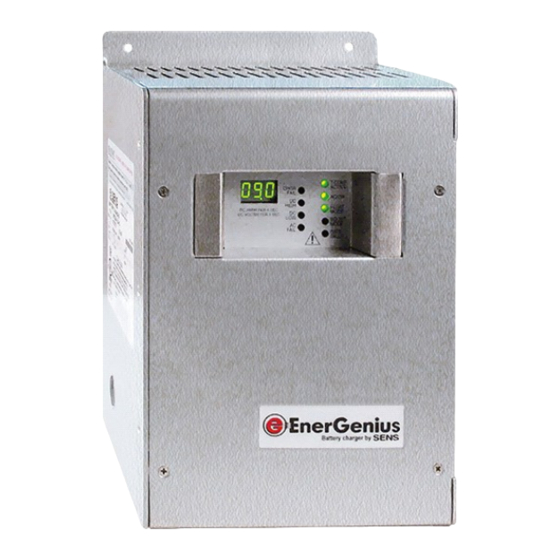
- Page 12 SENS EnerGenius NRG Technical Manual 12. CHECK OUT Green for temperature-corrected charger voltage Green for normal AC input Red for internal charger failure Red for excessive battery voltage DC Volt/Amp Meter Display Red for low battery voltage Red for low or missing AC input...
-
Page 13: Advanced Design Features
SENS EnerGenius NRG Technical Manual OPERATOR INSTRUCTIONS WARNING: NO OPERATOR SERVICEABLE PARTS INSIDE. DO NOT OPEN. COVER MUST BE IN PLACE DURING USE. USE THIS CHARGER FOR CHARGING LEAD-ACID OR NICKEL-CADMIUM BATTERIES ONLY. A. ADVANCED DESIGN FEATURES Battery Friendly: • Float and boost voltage selectable at install per specific battery vendor recommendations. - Page 14 SENS EnerGenius NRG Technical Manual age is either too high or too low, the charger enters a “lockout” period for approximately 10 seconds before attempting an automatic restart. • The “JUMP” feature (described in Section 11-F in this manual) may be used to allow the battery charger to over- ride the lockout and start charging a low-voltage discharged battery.
- Page 15 SENS EnerGenius NRG Technical Manual ITEM TEXT Meaning Troubleshooting CHGR FAIL Charger Fail Charger unable to provide charging current to bat- tery. Replace unit. AC input voltage is too low to supply proper cur- rent when load is applied. Control board is damaged and should be replaced.
- Page 16 SENS EnerGenius NRG Technical Manual TROUBLESHOOTING GUIDE—REPEATED BLOWN AC FUSE START: AC FAIL LED red INPUT SWITCH FUSE PROPERLY CONFIGURE CONFIGURED FOR STILL SELECTION SWITCH 115V BUT SOURCE BLOWS? IS 230V? AC VOLTS FUSE CORRECT CORRECT AC INPUT STILL (MEASURE WITH...
- Page 17 SENS EnerGenius NRG Technical Manual TROUBLESHOOTING GUIDE—AC FAIL ALARM START: AC FAIL LED red INPUT ALARM PROPERLY SELECTION STILL CONFIGURE SWITCH PROPERLY PRESENT? SELECTION SWITCH CONFIGURED? AC VOLTS AND ALARM FREQ CORRECT CORRECT AC INPUT STILL (MEASURE WITH SUPPLY PROBLEM...
- Page 18 SENS EnerGenius NRG Technical Manual TROUBLESHOOTING GUIDE—CHARGER FAIL ALARM START: CHGR FAIL LED red ALARM AC VOLTS LOW CORRECT AC INPUT STILL (MEASURE WITH SUPPLY PROBLEM PRESENT? MULTIMETER)? ALARM CONNECTORS STILL CONNECTIONS FIRMLY SEATED? PRESENT? ALARM REPLACE CIRCUIT STILL BOARD TRAY...
- Page 19 SENS EnerGenius NRG Technical Manual TROUBLESHOOTING GUIDE—DC HIGH ALARM START: DC HIGH LED red ALARM BATTERY RANGE ADJUST JUMPER STILL VOLTAGE JUMPER FOR 12V OR 24V PRESENT? PROPERLY SET? BATTERY CORRECT BATTERY/ ALARM DC VOLTS HIGH LOAD VOLTAGE STILL (MEASURE WITH...
- Page 20 SENS EnerGenius NRG Technical Manual TROUBLESHOOTING GUIDE—DC LOW ALARM START: DC LOW LED red ALARM BATTERY RANGE ADJUST JUMPER STILL VOLTAGE JUMPER FOR 12V OR 24V PRESENT? PROPERLY SET? BATTERY AC VOLTS AND ALARM FREQ CORRECT CORRECT AC INPUT STILL...
- Page 21 SENS EnerGenius NRG Technical Manual TROUBLESHOOTING GUIDE—BATTERY FAULT ALARM START: BATT FAULT LED red FIX LEADS THAT ARE TOO LONG, TOO SMALL, POOR- ALARM BATT FAULT LED HIGH RESISTANCE LY CONNECTED OR OPEN STILL SOLID RED IN CHARGER (SEE MANUAL FOR WIRE...
-
Page 22: Normal Set Up
SENS EnerGenius NRG Technical Manual C. NORMAL SET UP: 1. Apply AC power by closing the branch circuit breaker and any other disconnect devices. 2. The meter display should light immediately after power on. The green AC/ ON LED should be lighted. If a temperature sensor is present, either internal or remote, the green T-COMP (Temperature Compensation) LED should be lighted. - Page 23 Directives(s) and Standard(s). 6/7/2019 ________________________________________ ______________________ Sam Coleman Date Compliance Manager Stored Energy Systems, LLC STORED ENERGY SYSTEMS, LLC 1840 INDUSTRIAL CIRCLE, LONGMONT, COLORADO 80501 FAX 303.678.7504 303.678.7500 www.sens-usa.com email: info@sens-usa.com FORM-226 REV F DATE ISSUED: 6/7/2019...
- Page 24 Return Material Authorization (RMA) number provided by SENS. If, in SENS’ opinion, the problem can be rectified in the field, SENS may elect to ship replacement parts for customer installation instead of having the product returned to the factory.
Need help?
Do you have a question about the EnerGenius NRG24-10 and is the answer not in the manual?
Questions and answers