DCS BGB30-BQR Use And Care Manual
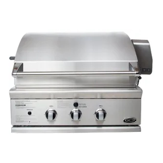
The professional 30” bgb grill
Hide thumbs
Also See for BGB30-BQR:
- Use and care manual (78 pages) ,
- Brochure & specs (2 pages) ,
- Specifications (2 pages)
Table of Contents
Advertisement
Available languages
Available languages
Advertisement
Chapters
Table of Contents

Subscribe to Our Youtube Channel
Related Manuals for DCS BGB30-BQR


Summary of Contents for DCS BGB30-BQR
- Page 1 THE PROFESSIONAL 30” BGB GRILL Use and Care Guide MODELS: BGB30-BQR...
-
Page 3: A Message To Our Customers
A MESSAGE TO OUR CUSTOMERS Thank you for selecting this DCS Professional “BGB” Series Grill. Because of this appliance’s unique features we have developed this Use & Care Guide. It contains valuable information on how to properly install, operate and maintain your new appliance for years of safe and enjoyable cooking. -
Page 4: Table Of Contents
CONTENTS SAFETY PRACTICES & PRECAUTIONS GRILL MODELS INSTALLATION Locating Grill / Built-in Clearances Built-in Construction Details 10-11 Cart Assembly Instructions 12-15 Gas Hook-up 16-19 Leak Testing Burner Adjustment Radiant Assembly Installer Checklist USING THE GRILL Lighting Instructions Grilling 25-26 USING THE ROTISSERIE 27-30 CARE &... -
Page 5: Safety Practices & Precautions
SAFETY PRACTICES & PRECAUTIONS IMPORTANT SAFETY NOTICE! Certain Liquid Propane dealers may fill liquid propane cylinders for use in the grill beyond cylinder filling capacity. This “Overfilling” may create a dangerous condition. “Overfilled” tanks can build up excess pressure. As a safety device, the tank pressure relief valve will vent propane gas vapor to relieve this excess pressure. - Page 6 SAFETY PRACTICES & PRECAUTIONS After a period of storage or non-use (such as over the winter), the gas grill should be checked for gas leaks, deterioration, proper assembly, and burner obstructions before using. Never let clothing, pot holders or other flammable materials come in contact with or get too close to any grate, burner or hot surface until it has cooled.
- Page 7 SAFETY PRACTICES & PRECAUTIONS When using the side burners always use flat bottomed pans which are large enough to cover the side burner. Adjust the flame so that it heats only the bottom of the pan to avoid ignition of clothing. Position handles inward away from open edges of the unit to avoid burns associated with unintentional spillovers.
-
Page 8: Grill Models
GRILL MODELS BGB30-BQR... -
Page 9: Installation
INSTALLATION LOCATING GRILL/BUILT-IN CLEARANCES LOCATION: When determining a suitable location take into account concerns such as exposure to wind, proximity to traffic paths and keeping any gas or electrical supply lines as short as possible and away from heat sources. Locate the grill only in a well ventilated area. - Page 10 INSTALLATION LOCATING GRILL/BUILT-IN CLEARANCES Clearances to Non-Combustible Construction*: A minimum of 3" clearance from the back of the grill to non-combustible construction is required for the purpose of allowing the lid to open fully. It is desirable to allow at least 6" rear and side clearance to non-combustible construction above the cooking surface for counter space.
- Page 11 If the grill is to be placed into a combustible enclosure, an approved insulated jacket is necessary. Insulated jackets are available from your dealer. Use only the DCS insulated jacket which has specifically been designed and tested for this purpose. Review the detail drawing shown (Fig. 04) and take into account the provisions shown for gas line hook-up clearance in the right rear corner.
-
Page 12: Built-In Construction Details
INSTALLATION BUILT–IN CONSTRUCTION DETAILS grill exhaust 3" (to non-combustible construction / minimum lid clearance) 12" (to combustible 13-3/4" construction) Bottom of support flange 10-1/16" 2" 22-3/4" 3/4" 25-1/2" Standard layout for non-combustible enclosure: Layout for insulated jacket only - combustible enclosure: NOTE: If using a backguard NOTE: If using a backguard apron or rear apron or rear wall, locate... -
Page 13: Built-In Construction Details
INSTALLATION BUILT–IN CONSTRUCTION DETAILS Access Doors Access Drawers Cutout dimensions Cutout dimensions Vent* Vent* Vent* 90º Cutout for Access Doors FIG. 05 FIG. 06 NOTE: The cutout of each corner should be 90 º angle in order for the access drawers NOTE: The cutout of each corner should be 90 º... -
Page 14: Cart Assembly Instructions
Your cart is packaged in one box. The box contains your Contents Qty. 30” grill cart and a universal hardware kit to be used for BGB30-BQR grill installation and may contain extra Machine hardware for your convenience. philip screws 10-24X1/2”... - Page 15 INSTALLATION CART ASSEMBLY INSTRUCTIONS STEP 1 Attach Side Shelf on the Right Side (left side is optional side burner location) 1. Attach shelf to right side of the cart using 1/4-20 nuts and bolts provided [leave out (1) bolt front side as shown below].
- Page 16 INSTALLATION CART ASSEMBLY INSTRUCTIONS Pinch Point FIG. 10 Lift grill over rear flange of cart (be FIG. 11 Grill head should rest over rear cart FIG. 12 Secure grill to rear of cart with (2) aware of pinch points). flange as shown above. phillips-head screws provided (10-24 x 1/2”).
-
Page 17: Cart Assembly Instructions
INSTALLATION CART ASSEMBLY INSTRUCTIONS STEP 5 Side tray adjustment 1. Take the tray and place it onto the handle at a upright position. Make sure the tray sits snugly around the handle. 2. Then tighten the rest of the loose bolts that were not tightened in Step 1. Side shelf adjustment 1. -
Page 18: Gas Hook-Up
(natural or LP) from your grill. TOTAL GAS CONSUMPTION OF THE GRILL WITH ALL BURNERS ON HI: BGB30-BQR - 64,000 Btu/hr The appliance and its individual shut-off valve must be disconnected from the gas supply piping system during any pressure testing of that system at test pressures in excess of 1/2 PSIG (3.5 kPa.) The appliance must be... -
Page 19: Lp Tank Requirements
INSTALLATION GAS HOOK-UP Connection: 1/2" NPT male with a 3/8" Flare adapter (included). LP Hose with a quick disconnect and fittings are included. Operating pressure: 11.0" W.C. CAUTION! Before connecting LP tank to regulator, check that all grill burners, side burners, and rotisserie valves are in the OFF position and open grill lid. - Page 20 If you intend to operate your Built-in grill on LP gas utilizing a 20 lb Type 1 cylinder, then the Built-in LP tank restraint must be installed prior to initial use of the grill. If you do not have one please contact DCS Customer Care at (888) 936-7872 for information on obtaining one.
- Page 21 INSTALLATION GAS HOOK-UP STEP 1 Place the tank restraint in the island (Fig. 25). STEP 2 Locate the tank restraint in the island within the recommended area (Fig. 24 and 26). STEP 3 Once located, secure to the bottom of the island using all eight hole locations provided on the restraint.
-
Page 22: Leak Testing
INSTALLATION LEAK TESTING GENERAL: Although all gas connections on the grill are leak tested at the factory prior to shipment, a complete gas tightness check must be performed at the installation site due to possible mishandling in shipment, or excessive pressure unknowingly being applied to the unit. -
Page 23: Burner Adjustment
INSTALLATION BURNER ADJUSTMENT GRILL BURNER AIR ADJUSTMENT: Each grill burner is tested and adjusted at the factory prior to shipment; however, variations in the local gas supply or a conversion from one gas type to another may make it necessary to adjust the burners. The flames of the burners (except the rotisserie burner) should be visually checked and compared to that of the drawing in Fig. -
Page 24: Radiant Assembly
INSTALLATION RADIANT ASSEMBLY RADIANT ASSEMBLY INSTALLATION: 1. Unpack ceramic rods and remove radiant (Fig. 34) from the unit. 2. Unlock radiant end cap by pushing it up with two fingers (Fig. 35). 3. Place 18 ceramic rods on the radiant (Fig. 36). 4. -
Page 25: Installer Checklist
NOTE: If any of the listed items are missing, contact DCS at (888) 936-7872. Please be prepared with your Model #, Serial # and description of item(s) that are missing. Tag location of Model # and Serial # Read all installation instructions in this manual to see if the unit has been properly installed. -
Page 26: Using The Grill
USING THE GRILL LIGHTING INSTRUCTIONS TO LIGHT THE GRILL BURNER: Open the grill lid before lighting. Turn all knobs to “OFF”. Turn the main gas supply on slowly. If you smell gas, shut-off gas supply and call for service. Push and hold the ignition button, turn the selected burner knob to “HI”. If burner does not light in 4 to 5 seconds, turn knob “OFF”... -
Page 27: Grilling
USING THE GRILL GRILLING GRILL: Each grill section consists of a large stainless steel burner, stainless steel heat baffles, a series of ceramic rods encased in a stainless steel radiant, and a stainless steel heat retaining grate. Each burner is rated at 25,000 Btu/hr. -
Page 28: Grilling
USING THE GRILL GRILLING IMPORTANT - Using the Grill: To season the grates, pour a tablespoon of vegetable oil on a soft cloth and rub on both sides of the grates. Only a light coating is needed and some smoke may be visible during the preheating. Grilling requires high heat for searing and proper browning. -
Page 29: Using The Rotisserie
USING THE ROTISSERIE The grill rotisserie system is designed to cook items from the back using infrared heat. The location of the burner allows the placement of the rotisserie basting pan (included) beneath the food to collect juices and drippings for basting and gravy. To flavor the contents of the basting pan, you can add herbs, onion, garlic, or spices. - Page 30 USING THE ROTISSERIE WARNING! Never have the grill burners (bottom burners) on during Rotisserie cooking. It will burn your meat and make it very dry. Use only one section at a time, grill or rotisserie. PREPARATION Recommended: Dental floss or butcher string, scissors, broiler pan (bottom only), pliers, instant read thermometer, foil, and hot pads.
- Page 31 USING THE ROTISSERIE TO LIGHT THE ROTISSERIE BURNER BEFORE COOKING: The location of the rotisserie burner makes it more susceptible to strong wind conditions, more so than the protected grill burners. For this reason, you should avoid operating the rotisserie during windy conditions. As an added safety feature we’ve equipped the burner with an automatic safety valve which will not allow gas to flow to the rotisserie burner unless the following conditions are present with the knob on: 1.
-
Page 32: Using The Rotisserie
USING THE ROTISSERIE COOKING ON ROTISSERIE 1. Place prepared rod into motor, lay across to other side in groove (Fig. 48). 2. Verify placement as shown in Fig. 49. 3. Ignite burner, start rotisserie motor, and keep on rotisserie valve on “high” for cooking all meats on the rotisserie. 4. -
Page 33: Care & Maintenance
CARE AND MAINTENANCE BATTERY REPLACEMENT: 1. Remove drip pan. 2. Open cart door (on cart model only) 3. Pull battery downwards (this may require use of pliers). 4. Re-install upward and push to snap - Fig. 52. (polarity is shown in Fig. 53). Note: Battery condition should be checked at least once a year. -
Page 34: Care & Maintenance
CARE AND MAINTENANCE direction of the grain. Specks of grease can gather on the surfaces of the stainless ELECTRODE (KEEP CLEAN) steel and bake on to the surface and give the appearance of rust. For removal use an abrasive pad (Scotch Brite is good) in conjunction with a stainless steel cleaner. Always rub in the direction of the grain. -
Page 35: Troubleshooting
Troubleshooting is for general purposes only. If the problem persists and you feel you require service, contact your dealer or the nearest authorized agency to perform service. Only authorized agencies can perform warranty service. Call DCS Customer Care at (888) 936-7872. GRILL WON’T LIGHT WHEN THE IGNITION BUTTON IS PUSHED: 1. -
Page 36: Service
SERVICE HOW TO OBTAIN SERVICE: For warranty service, please contact your local service provider or DCS Customer Care Representative at (888) 936-7872. Before you call, please have the following information ready: Model Number (can be found on the inside, right side panel behind the drip pan handle. See page 23.) Serial Number (can be found on the inside, right side panel behind the drip pan handle. -
Page 37: Warranty
WARRANTY LIMITED WARRANTY When you purchase a new DCS Grill by Fisher & Paykel, you automatically receive a One Year Limited Warranty covering parts and labor for the entire product, and a Five Year Comprehensive Warranty covering the burners, grill radiant assemblies, and drip pans. for servicing within the 48 mainland United States, Hawaii, Washington D.C. - Page 38 Please read your Use and Care Guide. If you then have any questions about operating the Product, need the name of your local DCS Authorized Service Agent, or believe the Product is defective and wish service under this Limited Warranty, please contact your dealer or call us at: TOLL FREE 1-888-936-7872 or contact us through our web site: www.dcsappliances.com.
- Page 39 LE GRIL DE SÉRIE PROFESSIONNELLE BGB 30 PO Manuel d'utilisation et d'entretien MODÈLES : BGB30-BQR...
- Page 40 À L'INTENTION DE NOS CLIENTS Nous vous remercions d'avoir choisi ce gril de la série professionnelle « BGB » de DCS. Nous avons conçu ce Manuel d'utilisation et d'entretien pour expliquer les fonctions uniques de ces appareils. Ce manuel contient des informations extrêmement utiles sur la façon correcte de faire fonctionner votre nouvel appareil et d'en faire...
- Page 41 TABLE DES MATIÈRES MESURES DE SÉCURITÉ ET DE PRÉCAUTION MODÈLES DE GRIL INSTALLATION Emplacement du gril et des dégagements 8-10 Détails d'une construction intégrée 11-12 Instructions de montage de chariot 13-16 Branchement du gaz 17-20 Test de détection des fuites Réglage du brûleur du gril L'ensemble du radiant Liste de contrôle de l'installateur...
-
Page 42: Mesures De Sécurité Et De Précaution
MESURES DE SÉCURITÉ ET DE PRÉCAUTION IMPORTANTE CONSIGNE DE SÉCURITÉ! Certains fournisseurs de propane liquide peuvent remplir les bonbonnes de propane liquide du gril au-delà de leur capacité. Ce trop-plein peut créer une situation dangereuse. Une accumulation de pression peut effet se produire dans les bouteilles trop remplies. En tant que dispositif de sécurité, la soupape de décharge évacue les vapeurs de gaz propane afin de diminuer l'excédent de pression. - Page 43 MESURES DE SÉCURITÉ ET DE PRÉCAUTION Ne rangez pas d'objets pouvant intéresser les enfants autour ou en dessous du gril, dans le chariot ou une enceinte de maçonnerie. Ne laissez jamais les enfants ramper à l'intérieur d'un chariot ou d'une enceinte. Il ne faut ni attacher ni connecter une bouteille de propane, ni déplacer ni modifier les raccords de gaz lorsque le gril fonctionne ou qu'il est chaud.
- Page 44 MESURES DE SÉCURITÉ ET DE PRÉCAUTION EMPLACEMENT DU GRIL FLUX D'ÉVENT DE SORTIE ÉVACUATION DU GRIL Le vent qui frappe le gril pendant son Si le vent est un utilisation, particu- problème, il lièrement les vents faut ajouter un 15 po min. soufflant dans ou coupe-vent.
- Page 45 MESURES DE SÉCURITÉ ET DE PRÉCAUTION Ayez un extincteur de classe ABC à portée de la main – ne tentez jamais d'éteindre un incendie de graisse avec de l'eau ou d'autres liquides. Pour éviter toute brûlure lors de la cuisson, utilisez des outils de barbecue à manches longs. Ne déplacez pas l'appareil durant son utilisation.
-
Page 46: Modèles De Gril
MODÈLES DE GRIL BGB30-BQR... -
Page 47: Installation
INSTALLATION EMPLACEMENT DU GRIL ET DES DÉGAGEMENTS EMPLACEMENT : Pour déterminer un emplacement approprié, vous devez tenir compte de plusieurs éléments : exposition au vent, proximité de chemins de circulation, nécessité de garder les conduites d'alimentation en gaz ou électrique le plus court possible et à... - Page 48 INSTALLATION EMPLACEMENT DU GRIL ET DES DÉGAGEMENTS Espaces de dégagement pour une construction non combustible *: Prévoyez une distance de 7,6 cm (3 po) minimum entre l'arrière du gril et la construction non combustible afin de pouvoir ouvrir le couvercle complètement. Il est conseillé de prévoir au moins 15,3 cm (6 po) de dégagement latéral et de l'arrière par rapport à...
- Page 49 Si le gril doit être placé dans une enceinte combustible, une enveloppe isolée homologuée est nécessaire. Des enveloppes isolées sont disponibles auprès de votre distributeur. Utilisez uniquement une enveloppe isolée DCS ayant été conçue et testée spécialement à cette fin. Analysez le schéma détaillé (Fig. 04) et tenez compte des dispositions à...
-
Page 50: Détails D'une Construction Intégrée
INSTALLATION DÉTAILS D'UNE CONSTRUCTION INTÉGRÉE évacuation du gril 7,6 cm/3 po (dégagement min.pour le couvercle avec une construction non combustible) 30,5 cm/12 po (dégagement avec une 34,93 cm/ construction combustible) 13 3/4 po Fond de la bride de soutien 25,56 cm/10 1/16po 5,08 cm/ 57,79 cm/22 3/4po 1,91cm/3/4 po... - Page 51 INSTALLATION DÉTAILS D'UNE CONSTRUCTION INTÉGRÉE PORTES D’ACCÈS - DIMENSIONS DES DECOUPES LES TIROIRS - DIMENSIONS DES DECOUPES Vent* Vent* Vent* 90º Découpe pour portes d'accès FIG. 06 FIG. 05 REMARQUE: La découpe de chaque coin doit être d'un angle REMARQUE: La découpe de chaque coin doit être d'un de 90 º...
-
Page 52: Instructions De Montage De Chariot
INSTALLATION INSTRUCTIONS DE MONTAGE DE CHARIOT Important! Lisez toutes les instructions avant de commencer. Évitez de sauter des étapes. MISE EN GARDE! Certaines pièces ont des bords coupants; faites attention lorsque vous manipulez les différents composants pour éviter de vous blesser. Veuillez lire les consignes de sécurité de ce manuel avant de commencer l'assemblage. Portez des gants. - Page 53 INSTALLATION INSTRUCTIONS DE MONTAGE DE CHARIOT ÉTAPE 1 Fixez la tablette latérale sur le côté droit (le côté gauche est l'emplacement du brûleur latéral en option) 1. Fixez la tablette au côté droit du chariot à l'aide d'écrous et de boulons 1/4-20 [laissez de côté (1) boulon sur l'avant tel qu'indiqué...
- Page 54 INSTALLATION INSTRUCTIONS DE MONTAGE DE CHARIOT Point de pincement FIG. 10 Placez le gril par-dessus la bride FIG. 11 La tête du gril doit reposer par- FIG.12 Fixez le gril à la partie arrière du chariot arrière du chariot (faites attention aux points dessus la bride arrière du chariot tel à...
- Page 55 INSTALLATION INSTRUCTIONS DE MONTAGE DE CHARIOT ÉTAPE 5 Réglage du plateau latéral 1. Saisissez le plateau et placez-le sur la poignée en position verticale. Assurez-vous que le plateau est bien assis sur la poignée. 2. Serrez ensuite le reste des boulons laissés desserrés à l'étape 1. Réglage de la tablette latérale 1.
-
Page 56: Branchement Du Gaz
(naturel ou propane) de votre gril. CONSOMMATION TOTALE DE GAZ DU GRIL, LES BRÛLEURS ÉTANT TOUS SUR HI : BGB30-BQR - 64 000 BTUH L'appareil et son robinet d'arrêt doivent être déconnectés du système d'alimentation en gaz durant les tests de pression lorsque celle-ci est supérieure à... - Page 57 INSTALLATION BRANCHEMENT DU GAZ Connexion : Raccord mâle 3/8 po NPT avec adaptateur évasé 3/8 po (inclus). Un tuyau de propane avec déconnexion rapide et des raccords sont inclus. Pression utile : 10,0 po C.E. MISE EN GARDE! Avant de connecter la bouteille de propane au régulateur, assurez-vous que tous les brûleurs et brûleurs latéraux, fumoirs et valves de rôtissoire sont en position OFF, puis ouvrez le couvercle du gril.
- Page 58 242232, avant d'utiliser le gril pour la première fois. Si vous n'avez pas ce dispositif, veuillez contacter le Service à la clientèle DCS en composant le (888) 936-7872 pour en obtenir un.
- Page 59 INSTALLATION BRANCHEMENT DU GAZ STEP 1 Placez le dispositif de retenue de bouteille dans l'îlot (Fig. 25). STEP 2 Situez le dispositif de retenue de bouteille dans l'îlot à l'intérieur de la zone recommandée (Fig. 24 et 26). STEP 3 Une fois situé, fixer sur le bas de l'îlot à...
-
Page 60: Test De Détection Des Fuites
INSTALLATION TEST DE DÉTECTION DES FUITES GÉNÉRALITÉS : Bien que toutes les connexions de gaz du gril soient testées en usine avant l'expédition, une vérification complète doit être effectuée sur le site d'installation, pour s'assurer qu'il n'y a pas de fuites, au cas où l'appareil aurait été... -
Page 61: Réglage Du Brûleur Du Gril
INSTALLATION RÉGLAGE DU BRÛLEUR DU GRIL RÉGLAGE D'AIR DU BRÛLEUR DU GRIL : Chaque brûleur du gril est testé et réglé en usine avant d'être expédié; toutefois, des variations au niveau de l'alimentation en gaz locale ou de la conversion d'un gaz à un autre peut nécessiter un nouveau réglage. Les flammes des brûleurs (excepté... -
Page 62: L'ensemble Du Radiant
INSTALLATION INSTALLATION DE L'ENSEMBLE DU RADIANT INSTALLATION DE L'ENSEMBLE DU RADIANT : 1. Déballez les tiges en céramique et retirez le radiant (Fig. 34) de l'appareil. 2. Déverrouillez le couvercle du radiant en le poussant de deux doigts (Fig. 35). 3. -
Page 63: Liste De Contrôle De L'installateur
REMARQUE : Si un des articles indiqués manque, contactez DCS au (888) 936-7872. Veuillez avoir le numéro de modèle, le numéro de série et la description du produit dont vous avez fait l'achat à portée de la main. -
Page 64: Utilisation Du Gril Instructions D'allumage
UTILISATION DU GRIL INSTRUCTIONS D'ALLUMAGE POUR ALLUMER LE BRÛLEUR DU GRIL : Ouvrez le couvercle du gril avant d'allumer. Mettez tous les boutons sur « OFF ». Ouvrez lentement l'alimen- tation en gaz. Si vous sentez une odeur de gaz, fermez le gaz et appelez le service technique. Enfoncez le bouton d'allumage et tournez le bouton du brûleur choisi à... -
Page 65: Cuisson Sur Gril
UTILISATION DU GRIL CUISSON SUR GRIL Chaque section du gril consiste en un gros brûleur en acier inoxydable, une série d'écrans thermiques en acier inoxydable, une série de tiges en céramique encastrées dans une radiant en acier inoxydable, et une grille adiathermique en acier inoxydable. - Page 66 UTILISATION DU GRIL CUISSON SUR GRIL (suite) IMPORTANT Utilisation du gril : Pour traiter les grilles, versez une cuillère à soupe d'huile végétale sur un chiffon doux et frottez les deux côtés des grilles. Il suffit d'un léger film et de la fumée risque d'être visible pendant le préchauffage. La cuisson sur gril exige un feu vif pour rôtir les aliments et les braiser correctement.
-
Page 67: Utilisation De La Rôtissoire
UTILISATION DE LA RÔTISSOIRE Le système de rôtissoire de gril est conçu pour cuire les aliments par l'arrière, au moyen d'une chaleur à infrarouge. L'emplacement du brûleur permet de placer la cuvette d'arrosage de la rôtissoire (incluse) sous les aliments afin de recueillir les jus et les gouttes qui serviront à... - Page 68 UTILISATION DE LA RÔTISSOIRE AVERTISSEMENT! N'allumez jamais les brûleurs du gril (brûleurs inférieurs) lorsque vous utilisez la rôtissoire. Cela brûlerait la viande et la rendrait très sèche. Utilisez une section à la fois seulement, soit le gril, soit la rôtissoire. PRÉPARATION Recommandé...
- Page 69 UTILISATION DE LA RÔTISSOIRE POUR ALLUMER LE BRÛLEUR DE RÔTISSERIE AVANT DE FAIRE CUIRE : L'emplacement du brûleur de rôtissoire le rend plus susceptible aux vents forts que les brûleurs de gril qui sont protégés. Pour cette raison, évitez de faire fonctionner la rôtissoire s'il vente. Par mesure de sécurité supplé- mentaire, nous avons équipé...
- Page 70 UTILISATION DE LA RÔTISSOIRE CUISSON SUR LA RÔTISSOIRE 1. Insérez le tournebroche préparé dans le moteur et sur l'autre côté, dans la gorge (Fig. 48). 2. Vérifiez le bon emplacement conformément à la figure 49. 3. Allumez le brûleur, démarrez le moteur de la rôtissoire, et conservez la valve de rôtisserie sur « High » pour faire cuire toutes les viandes sur la rôtisserie.
-
Page 71: Entretien Et Nettoyage
ENTRETIEN ET NETTOYAGE REMPLACEMENT DE LA PILE : 1. Retirez le ramasse-gouttes. 2. Ouvrez la porte du chariot (modèle à chariot seulement). 3. Tirez la pile vers le bas (servez-vous d'une pince aubesoin). 4. Remettez-la en place vers le haut et poussez jusqu'à entendre un déclic, Fig. - Page 72 ENTRETIEN ET NETTOYAGE ACIER INOXYDABLE : ÉLECTRODE Le gril est fait d'acier inoxydable non magnétique. Après l'utilisation initiale, (DOIT ÊTRE GARDÉ PROPRE) certaines parties du gril peuvent se décolorer à cause de la chaleur intense dégagée par les brûleurs. Ceci est normal. On trouve toute sorte de nettoyants pour acier inoxydable sur le marché.
- Page 73 ENTRETIEN ET NETTOYAGE L'orifice doit être bien placé à l'intérieur du trou du venturi. 0.95 cm/3/8 po min. Panneau des valves Bouton Venturi de brûleur Valve de réglage FIG. 57 Faites très attention de ne pas déranger la position initiale de l'obturateur d'air (sauf en cas de réajustement). Abaissez l'arrière du brûleur dans les découpes, sur le canal de support, à...
-
Page 74: Dépannage
Seuls les centres de service agréés peuvent entreprendre un service sous garantie. Appelez le centre de service à la clientèle DCS au (888) 936-7872. LE GRIL NE S'ALLUME PAS LORSQU'ON ENFONCE LE BOUTON D'ALLUMAGE : 1. -
Page 75: Service
SERVICE POUR L'OBTENTION DU SERVICE DE GARANTIE : Pour le service sous garantie, contactez votre distributeur ou le Centre de service à la clientèle DCS au (888) 936-7872. Avant d'appeler, veuillez avoir les informations suivantes à portée de main : Numéro de modèle (peut se trouver sur le panneau latéral intérieur droit, derrière la poignée du ramasse-gouttes. -
Page 76: Garantie
Cette garantie s'applique à l'acheteur initial et à tous les propriétaires successifs du produit dans la mesure où il s'agit d'un produit acheté pour une utilisation à domicile normale. Tout service couvert par cette garantie limitée sera assuré par Fisher & Paykel Appliances Inc. ou son agent de service DCS agréé durant les heures d'ouverture normales. - Page 77 Veuillez consulter le guide d'utilisation et d’entretien. Si vous avez des questions concernant l'utilisation du produit, que vous cherchez le nom de l'agent de service DCS agréé local ou que pensez que le produit est défectueux et désirez le faire réparer dans le cadre de cette garantie limitée, veuillez contacter votre distributeur ou nous appeler au numéro suivant :...
- Page 78 REMARQUE...
- Page 80 Fisher & Paykel Appliances, Inc. 5900 Skylab Road, Huntington Beach, CA 92647 Customer Care: 888.936.7872 Fax: 714.372.7003 www.dcsappliances.com As product improvement is an ongoing process, we reserve the right to change specifications or design without notice. Nous améliorons constamment ses produits et se réserve le droit de modifier les spécifications ou la conception de ses produits sans aucun préavis.
Need help?
Do you have a question about the BGB30-BQR and is the answer not in the manual?
Questions and answers