Table of Contents
Advertisement
Model(s):
IDV4833IT, IDV4833ILT,
IDV4833IH, IDV4833ILH,
IDV6247IT, IDV6247ILT,
IDV6247IH, IDV6247ILH
• Important operating and
maintenance instructions
included.
WARNING
If the information in these instruc-
tions is not followed exactly, a
fi re may result causing property
damage, personal injury, or death.
• Do not store or use gasoline or other fl am-
mable vapors and liquids in the vicinity of
this or any other appliance.
• What to do if you smell gas:
- Do not try to light any appliance.
- Do not touch any electrical switch. Do not
use any phone in your building.
- Immediately call your gas supplier from
a neighbor's phone. Follow the gas
supplier's instructions.
- If you cannot reach your gas supplier, call
the fi re department.
• Installation and service must be performed
by a qualifi ed installer, service agency, or
the gas supplier.
This appliance may be installed as an OEM installation
in manufactured home (USA only) or mobile home and
must be installed in accordance with the manufacturer's
instructions and the manufactured home construction and
safety standard, Title 24 CFR, Part 3280 or Standard for
Installation in Mobile Homes, CAN/CSA Z240MH.
This appliance is only for use with the type(s) of gas
indicated on the rating plate.
CAUTION
DO NOT DISCARD THIS MANUAL
Read, understand and follow
•
these instructions for safe
installation and operation.
Heatilator • ICON DV-IDV Series • 4042-575 • Rev K • 11/08
Leave this manual with
•
party responsible for
use and operation.
WARNING
HOT SURFACES!
Glass and other surfaces are hot during
operation and cool down.
Hot glass will cause burns.
• Do not touch glass until it is cooled
• NEVER allow children to touch glass
• Keep children away
• CAREFULLY SUPERVISE children in same room as
appliance.
• A l e r t c h i l d r e n a n d a d u l t s t o h a z a r d s o f h i g h
temperatures.
High temperatures may ignite clothing or other
fl ammable materials.
• Keep clothing, furniture, draperies and other combustibles
away.
This appliance has been supplied with an integral
barrier to prevent direct contact with the fi xed glass
panel. Do NOT operate the appliance with the barrier
removed.
Contact your dealer or Hearth & Home Technologies if the
barrier is not present or help is needed to properly install one.
In the Commonwealth of Massachusetts installation must
be performed by a licensed plumber or gas fi tter;
See Table of Contents for location of additional
Commonwealth of Massachusetts requirements.
Installation and service of this appliance should be performed
by qualifi ed personnel. Hearth & Home Technologies suggests
NFI certifi ed or factory-trained professionals, or technicians
supervised by an NFI certifi ed professional.
Owner's Manual
Installation and Operation
1
Advertisement
Table of Contents

Related Manuals for Heatilator Gas Fireplace IDV4833IH


Summary of Contents for Heatilator Gas Fireplace IDV4833IH
- Page 1 Model(s): IDV4833IT, IDV4833ILT, IDV4833IH, IDV4833ILH, IDV6247IT, IDV6247ILT, IDV6247IH, IDV6247ILH • Important operating and maintenance instructions included. WARNING If the information in these instruc- tions is not followed exactly, a fi re may result causing property damage, personal injury, or death. •...
-
Page 2: Congratulations
Read this manual before installing or operating this appliance. Please retain this owner’s manual for future reference. A. Congratulations Congratulations on selecting a Heatilator gas fi replace, an elegant and clean alternative to wood burning fi replaces. The Heatilator gas fi replace you have selected is designed to provide the utmost in safety, reliability, and effi... -
Page 3: Table Of Contents
Safety Alert Key: • DANGER! Indicates a hazardous situation which, if not avoided will result in death or serious injury. • WARNING! Indicates a hazardous situation which, if not avoided could result in death or serious injury. • CAUTION! Indicates a hazardous situation which, if not avoided, could result in minor or moderate injury. •... - Page 4 14 Appliance Setup A. Remove Shipping Materials B. Remove Fixed Glass Assembly C. Remove Materials Shipped Inside Firebox D. Clean the Appliance E. Accessories Heat-Zone-Gas G. Refractory H. Install the Logs Place Lava Rock and Rockwool Glass Panel Assembly K. Decorative Firescreen, Refractory Shields and Lower Decorative Front Face Installing External Refractories M.
-
Page 5: Warranty
B. Warranty Hearth & Home Technologies LIMITED WARRANTY Hearth & Home Technologies (“HHT”) and its respective brands extends the following warranty for HHT gas, wood, pellet and electric appliances purchased from an authorized HHT dealer and installed in the United States of America or Canada. - Page 6 B. Limited Lifetime Warranty (continued) This limited warranty does not extend to or include surface fi nish on the appliance or terminations, door gasketing, glass gasketing, glass discoloration, fi rebrick, pellet logs, kaowool or other ceramic insulating materials. Rust and/or corrosion on any of the metal surfaces, cast iron components, baffl...
-
Page 7: Listing And Code Approvals
Listing and Code Approvals A. Appliance Certifi cation MODELS: LABORATORY: Underwriters Laboratories, Inc. (UL) TYPE: Vented Gas Fireplace Heaters STANDARD: ANSI Z21.88-2002•CSA2.33-M2002•UL307B This product is listed to ANSI standards for “Vented Gas Fireplace Heaters” and applicable sections of “Gas Burn- ing Heating Appliances for Manufactured Homes and Recreational Vehicles”, and “Gas Fired Appliances for Use at High Altitudes”. -
Page 8: Requirements For The Commonwealth Of Massachusetts
Note: The following requirements reference various Massachusetts and national codes not contained in this document. H. Requirements for the Commonwealth of Massachusetts For all side wall horizontally vented gas fueled equipment installed in every dwelling, building or structure used in whole or in part for residential purposes, including those owned or operated by the Commonwealth and where the side wall exhaust vent termination is less than seven (7) -
Page 9: User Guide
Operating Instructions A. Gas Fireplace Safety WARNING HOT SURFACES! Glass and other surfaces are hot during operation and cool down. Hot glass will cause burns. • Do not touch glass until it is cooled • NEVER allow children to touch glass •... -
Page 10: Clear Space
C. Clear Space WARNING! DO NOT place combustible objects in front of the fi replace or block louvers. High temperatures may start a fi re. See Figure 2.2. Avoid placing candles and other heat-sensitive objects on mantel or hearth. Heat may damage these objects. Clear space 3 ft (914 mm) in front of appliance Figure 2.2... -
Page 11: Lighting Instructions (Ipi)
H. Lighting Instructions (IPI) • For normal use, activate/deactivate your fi replace with the wall switch or remote control. • The IPI system may be operated with two D-cell batteries. When using batteries, unplug the transformer. To prolong battery life, remove them when using the transformer. •... -
Page 12: After Fireplace Is Lit
I. After Fireplace is Lit Initial Break-in Procedure • The fireplace should be run three to four hours continuously on high. • Turn the fi replace off and allow it to completely cool. • Remove fi xed glass assembly. See Section 14.J. •... -
Page 13: Maintenance And Service
Maintenance and Service Any safety screen or guard removed for servicing must be replaced prior to operating the fi replace. When properly maintained, your fi replace will give you many years of trouble-free service. We recommend an- nual service by a qualifi ed service technician. A. -
Page 14: Maintenance Tasks-Qualifi Ed Service Technician
B. Maintenance Tasks-Qualifi ed Service Technician The following tasks must be performed by a qualifi ed service technician. Gasket Seal and Glass Assembly Inspection Frequency: Annually By: Qualifi ed Service Technician Tools needed: Protective gloves, drop cloth and a stable work surface. -
Page 15: Getting Started
Getting Started A. Typical Appliance System NOTICE: Illustrations and photos refl ect typical installations and are for design purposes only. Illustrations/diagrams are not drawn to scale. Actual product may vary from pictures in manual Noncombustible roof flashing maintains minimum clearance around pipe (SECTION 10) Vent Pipe (SECTIONS 7, 8, 10) -
Page 16: Design And Installation Considerations
B. Design and Installation Considerations Heatilator direct vent gas appliances are designed to op- erate with all combustion air siphoned from outside of the building and all exhaust gases expelled to the outside. No additional outside air source is required. Installation MUST comply with local, regional, state and national codes and regulations. -
Page 17: Framing And Clearances
Framing and Clearances A. Select Appliance Location When selecting a location for the appliance it is important to consider the required clearances to walls (see Figure 5.1). WARNING! Risk of Fire or Burns! Provide adequate clearance around air openings and for service access. Due to high temperatures, the appliance should be located out of traffi... -
Page 18: Construct The Appliance Chase
B. Construct the Appliance Chase A chase is a vertical box-like structure built to enclose the gas appliance and/or its vent system. In cooler climates the vent should enclosed inside the chase. NOTICE: Treatment of ceiling fi restops and wall shield fi... -
Page 19: Mantel And Wall Projections
D. Mantel and Wall Projections WARNING! Risk of Fire! Comply with all minimum clear- ances to combustibles as specifi ed. Framing or fi nishing material closer than the minimums listed must be construct- ed entirely of noncombustible materials (i.e., steel studs, concrete board, etc). -
Page 20: Termination Locations
Termination Locations A. Vent Termination Minimum Clearances WARNING Fire Risk. Maintain vent clearance to combustibles as specifi ed. • DO NOT pack air space with insulation or other materials. Failure to keep insulation or other materials away from vent pipe may cause overheating and fi re. 20 in. - Page 21 Measure vertical clearances from this surface Measure horizontal clearances from this surface. Dimension Descriptions A Clearance above the ground, a veranda, porch, deck or balcony - 12 in. (30 cm) minimum. * B Clearance to window or door that may be opened – 10,000 BTUs or less, 6 in.
-
Page 22: Vent Information And Diagrams
Vent Information and Diagrams A. Approved Pipe This appliance is approved for use with Hearth & Home Technologies DVP venting systems. Refer to Section 16.B. for vent component information. DO NOT mix pipe, fi ttings or joining methods from differ- ent manufacturers. -
Page 23: Vent Diagrams
E. Vent Diagrams To replace the fi rst starter elbow with two 45° elbows, refer to Figure 7.4. All other 90° elbows can be replaced with two 45° elbows. General Rules: • SUBTRACT 3 ft. from the total H measurement for each 90°... -
Page 24: Two Elbows
1. Top Vent - Horizontal Termination - (continued) Two 45° Elbows replacing One 90° Elbow Figure 7.4 Two Elbows Note: For corner installations: A 6 in. (152 mm) section of straight pipe may need to be attached to the appliance before a 90º elbow, to allow the vent pipe to clear the top standoffs. - Page 25 1. Top Vent - Horizontal Termination - (continued) Three Elbows Figure 7.6 Heatilator • ICON DV-IDV Series • 4042-575 • Rev K • 11/08 min. max. 0.30 7.32 Installed Vertically max. 5.79...
-
Page 26: Top Vent - Vertical Termination
2. Top Vent - Vertical Termination NOTICE: If installing a vertical vent/termination off the top of the appliance, the fl ue restrictor should be used. No Elbow 12 ft (3.66 m) min. 60 ft (18.29 m) max. Figure 7.7 Two Elbows 12 ft (3.66 m) min. -
Page 27: Three Elbows
2. Top Vent - Vertical Termination - (continued) Three Elbows Figure 7.9 Maximum horizontal run is 100% of vertical, but cannot exceed 26 ft (7.92 m) 12 ft (3.66 m) min. 60 ft (18.29 m) max. Heatilator • ICON DV-IDV Series • 4042-575 • Rev K • 11/08... -
Page 28: Vent Clearances And Framing
Vent Clearances and Framing A. Pipe Clearances to Combustibles WARNING! Risk of Fire! Maintain air space clearance to vent. DO NOT pack insulation or other combustibles: • Between ceiling fi restops • Between wall shield fi restops • Around vent system Failure to keep insulation or other material away from vent pipe may cause over heating and fi... -
Page 29: Install The Ceiling Firestop
C. Install the Ceiling Firestop A ceiling fi restop MUST be used between fl oors and at- tics. • Frame an opening 10 in. by 10 in. (254 mm by 254 mm) whenever the vent penetrates a ceiling/fl oor (see Figure 8.3). -
Page 30: Install Attic Insulation Shield
D. Install Attic Insulation Shield WARNING! Fire Risk. DO NOT allow loose materials or insulation to touch vent. Hearth & Home Technologies Inc. requires the use of an attic shield. The National Fuel Gas Code ANSI Z223.1 and NFPA 54 requires an attic shield constructed of 26 gauge minimum metal that extends at least 2 in. -
Page 31: Appliance Preparation
Appliance Preparation A. Secure and Level the Appliance WARNING! Risk of Fire! Prevent contact with: • Sagging or loose insulation • Insulation backing or plastic • Framing and other combustible materials Block openings into the chase to prevent entry of blown-in insulation. -
Page 32: Install Vent Pipe
Install Vent Pipe A. Assemble Vent Sections Attach Pipe to the Firebox Assembly Note: The end of the pipe sections with the lanced tabs will face towards the appliance. Attach the fi rst pipe section to the starting collar: • Lanced pipe end to the starting collar •... -
Page 33: Assemble Slip Sections
B. Assemble Slip Sections WARNING! Risk of Fire or Asphyxiation! Overlap pipe sections at least 1 1/2 in. (38 mm). Secure slip sections with two screws which must not exceed 1/2 in. (13 mm) in length. Use the pilot holes. Pipe could separate if not properly joined. -
Page 34: Disassemble Vent Sections
D. Disassemble Vent Sections • Rotate either section (see Figure 10.9) so the seams on both pipe sections are aligned as shown in Figure 10.10. • Pull carefully to separate the pieces of pipe. Figure 10.9 Rotate Seams for Disassembly Figure 10.10 Align and Disassemble Vent Sections E. -
Page 35: Assemble And Install Storm Collar
F. Assemble and Install Storm Collar CAUTION! Risk of Cuts, Abrasions or Flying Debris. Wear protective gloves and safety glasses during installa- tion. Sheet metal edges are sharp. • Connect both halves of the storm collar with two screws (see Figures 10.13-10.14). •... -
Page 36: Install Rf4-8
G. Install RF4-8 The RF4-8 may be used in place of the roof fl ashing and storm collar. Pipe must be supported within 12 in. (305 mm) of the roofl ine using plumbers strapping or an SLP-FS when us- ing the RF4-8 Flashing. Refer to Sect. 10.C. Secure the Vent Sections. -
Page 37: Install Vertical Termination Cap
H. Install Vertical Termination Cap • Attach the vertical termination cap by sliding the inner collar of the cap into the inner fl ue of the pipe section while placing the outer collar of the cap over the outer fl ue of the pipe section. •... -
Page 38: Install Horizontal Termination Cap
J. Install Horizontal Termination Cap WARNING! Risk of Fire! The telescoping fl ue section of the termination cap MUST be used when connecting vent. • 1-1/2 (38 mm) minimum overlap of fl ue telescoping section is required. Failure to maintain overlap may cause overheating and fi... -
Page 39: Gas Information
11 11 Gas Information A. Fuel Conversion • Make sure the appliance is compatible with available gas types. • Conversions must be made by a qualified service technician using Hearth & Home Technologies specifi ed and approved parts. B. Gas Pressure •... -
Page 40: Electrical Information
Electrical Information A. Wiring Requirements NOTICE: This appliance must be electrically wired and grounded in accordance with local codes or, in the absence of local codes, with National Electric Code ANSI/NFPA 70-latest edition or the Canadian Electric Code CSA C22.1. •... -
Page 41: Junction Box Installation
E. Junction Box Installation If the junction box is being wired from OUTSIDE of the appliance (preferred method): • Remove two screws that attach junction box and bracket to appliance. See Figure 12.2. • Feed an appropriate length of romex through plastic romex connector. -
Page 42: Finishing
Finishing A. Mantel and Wall Projections WARNING! Risk of Fire! Comply with all minimum clear- ances to combustibles as specifi ed. Framing or fi nishing material closer than the minimums listed must be construct- ed entirely of noncombustible materials (i.e., steel studs, concrete board, etc). -
Page 43: Noncombustible Finishing Material
C. Noncombustible Finishing Material Finishing Material (Finished Opening Width) (Finished Opening Width) Figure 13.4 Finished Fireplace Opening Finishing Material (Finished Opening Height) Heatilator • ICON DV-IDV Series • 4042-575 • Rev K • 11/08 Model IDV4833 inches 34 1/2 IDV6247 inches 1194... -
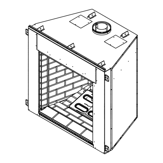
Page 44: Appliance Setup
Appliance Setup A. Remove Shipping Materials Remove shipping materials from inside or underneath the fi rebox. • Front refractory (three pieces) package shipped in front of glass. • Lower decorative front face, left and right refractory shields shipped on top of front refractory box. •... -
Page 45: Install The Logs
H. Install the Logs • Base logs are pre-installed. • Place three top logs: Place slot in bottom of top log over pin in top of base log. Align opposite end of log with white notched area in top of base log. Repeat for each top log. See Figures 12.1 through 12.6. -
Page 46: Place Lava Rock And Rockwool
I. Place Lava Rock and Rockwool WARNING! Risk of Explosion! Follow rockwool placement instructions. DO NOT place rockwool directly over burner ports. Replace rockwool material annually. Improperly placed rockwool interferes with proper burner operation. Rockwool and lava rock are shipped with this gas appli- ance •... -
Page 47: Glass Panel Assembly
J. Glass Panel Assembly Removing/Replacing Glass Assembly WARNING! Risk of Asphyxiation! Handle fi xed glass assembly with care. Inspect the gasket to ensure it is undamaged and inspect the glass for cracks, chips or scratches. • DO NOT strike, slam or scratch glass. •... -
Page 48: Decorative Firescreen, Refractory Shields And Lower Decorative Front Face
K. Decorative Firescreen, Refractory Shields and Lower Decorative Front Face • Install the decorative fi rescreen by fi rst inserting the left side of the screen rod into the horseshoe-shaped cradle (see Figure 12.11) • Rotate the right side of the rod up and into the cradle on the right (see Figure 12.12). -
Page 49: Installing External Refractories
L. Installing External Refractories Open Refractory Package (Figure 12.17) • 1 - LH side refractory panel • 1 - RH side refractory panel • 1 - Front hearth refractory panel Notches indicate top of refractory Right Left Front Hearth Figure 12.17 Refractory Pieces Install Side Refractories •... -
Page 50: Air Shutter Setting
M. Air Shutter Setting Air shutter settings should be adjusted by a qualifi ed installer at the time of installation. The air shutter is set at the factory for minimum vertical vent run. Adjust air shut- ter for longer vertical runs. See Figure 12.24. •... -
Page 51: Troubleshooting
Troubleshooting With proper installation, operation, and maintenance your gas appliance will provide years of trouble-free service. If you do experience a problem, this troubleshooting guide will assist a qualifi ed service technician in the diagnosis of a problem and the corrective action to be taken. This troubleshooting guide can only be used by a qualifi ed service technician. Con- tact your dealer to arrange a service call by a qualifi... - Page 52 Intellifi re Ignition System - (continued) Symptom 4. Pilot lights but continues A. A shorted or loose connection to spark, and main burner in fl ame sensing rod. will not ignite. (If the pilot continues to spark after the pilot fl ame has been lit, fl...
-
Page 53: Reference Materials
Reference Materials A. Appliance Dimension Diagram Dimensions are actual appliance dimensions. Use for reference only. For framing dimensions and clearances refer to Section 5. Model # IDV4833I IDV6247I Figure 16.1 Appliance Dimensions 21-1/2 in. 546 mm Electric Line 2-1/4 in. 57 mm 46-1/2 27-5/8... -
Page 54: Vent Components Diagrams
B. Vent Components Diagrams Pipe DVP4 DVP6 Effective DVP12 Height/Length DVP24 DVP36 DVP48 DVP6A DVP12A DVP Pipe (see chart) Assembled Height: 24 in./610 mm Diameter: 10 in./254 mm DVP-AS2 10 in. (254 mm) 5 in. (127 mm) DVP-HVS Vent Support Figure 16.2 DVP Vent Components Effective Height/Length inches... - Page 55 B. Vent Components Diagrams (continued) 13-1/4 in. (367 mm) 24-5/8 in. (698 mm) (625 mm) RF6M Roof Flashing Multi-pak 13-3/4 in. (349 mm) 13-3/4 in. (349 mm) Trap Cap Brick Extension DVP-TRAPFL Flashing 26 in. (660 mm) DVP-HSM-B Extended Heat Shield Figure 16.3 DVP Vent Components 27-1/2 in.
- Page 56 B. Vent Components Diagrams (continued) 1-1/2 in. (38 mm) 14 in. (356 mm) 12 in. (305 mm) DVP-TB1 Basement Vent Cap 7-1/4 in. (184 mm) 5-1/4 in. (133 mm) DVP-TVHW Vertical Termination Cap (High wind) 16-7/8 in. (429 mm) 12 in. (305 mm) 7-1/8 in.
- Page 57 B. Vent Components Diagrams (continued) Note: Heat shields MUST overlap by a minimum of 1-1/2 in. (38 mm). The heat shield is designed to be used on a wall 4 in. to 7-1/4 in. (102 mm to 184 mm) thick. If wall thickness is less than 4 in. (102 mm) the existing heat shields must be field trimmed.
- Page 58 B. Vent Components Diagrams (continued) 15 in. (381 mm) Effective Length 5-3/4 to 8-3/8 in. 146 to 213 mm Figure 16.6 DVP Vent Components Fillers DVP-TRAP to DVP-HPC Side Filler Kit 8-1/8 in. 13 in. (206 mm) (330 mm) DVP-HRC-SS 5-1/2 in.
-
Page 59: Service Parts
C. Service Parts Heatilator • ICON DV-IDV Series • 4042-575 • Rev K • 11/08... - Page 60 C. Service Parts (continued) Heatilator • ICON DV-IDV Series • 4042-575 • Rev K • 11/08...
- Page 61 C. Service Parts (continued) Heatilator • ICON DV-IDV Series • 4042-575 • Rev K • 11/08...
- Page 62 C. Service Parts (continued) Heatilator • ICON DV-IDV Series • 4042-575 • Rev K • 11/08...
-
Page 63: Optional Components
D. Optional Components Part # Description DF-PORT33-BK Portfolio black decorative front DF-PORT33-BZ Portfolio bronze decorative front DF-PORT47-BK Portfolio black decorative front DF-PORT47-BZ Portfolio bronze decorative front DF-SAL33-BK Salem black decorative front DF-SAL33-BZ Salem bronze decorative front DF-SAL47-BK Salem black decorative front DF-SAL47-BZ Salem bronze decorative front WSK-MLT-HTL... -
Page 64: Contact Information
E. Contact Information Please contact your Heatilator dealer with any questions or concerns. ________________________________________________________________________________ ________________________________________________________________________________ ________________________________________________________________________________ ________________________________________________________________________________ ________________________________________________________________________________ ________________________________________________________________________________ ________________________________________________________________________________ ________________________________________________________________________________ ________________________________________________________________________________ • Important operating a n d m a i n t e n a n c e instructions included. This product may be covered by one or more of the following patents: (United States) 4593510, 4686807, 4766876, 4793322, 4811534, 5000162, 5016609, 5076254, 5113843, 5191877, 5218953, 5263471, 5328356, 5341794, 5347983, 5429495, 5452708, 5542407, 5601073, 5613487, 5647340, 5688568, 5762062, 5775408, 5890485, 5931661, 5941237, 5947112, 5996575, 6006743, 6019099, 6048195, 6053165, 6145502, 6170481, 6237588,...
Need help?
Do you have a question about the Gas Fireplace IDV4833IH and is the answer not in the manual?
Questions and answers