Table of Contents
Advertisement
Quick Links
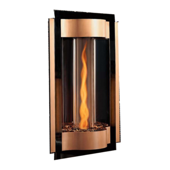
Model:
Cyclone-BN
Cyclone-BC
• Important operating
a n d m a i n t e n a n c e
instructions included.
WARNING: If the information in these
instructions is not followed exactly, a fi re
or explosion may result causing property
damage, personal injury, or death.
• Do not store or use gasoline or other fl am-
mable vapors and liquids in the vicinity of
this or any other appliance.
• What to do if you smell gas
- Do not try to light any appliance
- Do not touch any electrical switch. Do not
use any phone in your building.
- Immediately call your gas supplier from a
neighbor's phone. Follow the gas suppli-
er's instructions.
- If you cannot reach your gas supplier, call
the fi re department.
• Installation and service must be performed
by a qualifi ed installer, service agency, or the
gas supplier.
This appliance may be installed as an OEM installation in
manufactured home (USA only) or mobile home and must be
installed in accordance with the manufacturer's instructions and
the manufactured home construction and safety standard, Title
24 CFR, Part 3280 or Standard for Installation in Mobile Homes,
CAN/CSA Z240MH.
This appliance is only for use with the type(s) of gas indicated
on the rating plate.
CAUTION
DO NOT DISCARD THIS MANUAL
• Read, understand and follow
these instructions for safe
installation and operation.
Heat & Glo • Cyclone-BN, Cyclone-BC • 2073-900 Rev. N • 10/08
Owner's Manual
Installation and Operation
• Leave this manual with
party responsible for use
and operation.
WARNING
HOT SURFACES!
Glass and other surfaces are hot during
operation AND cool down.
Hot glass will cause burns.
• DO NOT touch glass until it is cooled
• NEVER allow children to touch glass
• Keep children away
• CAREFULLY SUPERVISE children in same room as
fi replace.
• Alert children and adults to hazards of high temperatures.
High temperatures may ignite clothing or other fl ammable
materials.
• Keep clothing, furniture, draperies and other fl ammable
materials away.
This appliance has been supplied with an integral barrier
to prevent direct contact with the fi xed glass panel. DO
NOT operate the appliance with the barrier removed.
Contact your dealer or Hearth & Home Technologies if the
barrier is not present or help is needed to properly install one.
In the Commonwealth of Massachusetts:
• installation must be performed by a licensed plumber
or gas fi tter;
See Table of Contents for location of additional
Commonwealth of Massachusetts requirements.
Installation and service of this appliance should be
performed by qualifi ed personnel. Hearth & Home
Technologies suggests NFI certifi ed or factory trained
professionals, or technicians supervised by an NFI
certifi ed professional.
1
Advertisement
Table of Contents

Related Manuals for Heat & Glo Cyclone-BC


Summary of Contents for Heat & Glo Cyclone-BC
- Page 1 CAN/CSA Z240MH. This appliance is only for use with the type(s) of gas indicated on the rating plate. Heat & Glo • Cyclone-BN, Cyclone-BC • 2073-900 Rev. N • 10/08 CAUTION DO NOT DISCARD THIS MANUAL • Read, understand and follow these instructions for safe installation and operation.
-
Page 2: Homeowner Reference Information
MAX. INPU T BTUH: MIN. INPU T BTUH: ORIFICE SIZE: Heat & Glo • Cyclone-BN, Cyclone-BC • 2073-900 Rev. N • 10/08 Congratulations This Owner’s Manual should be retained for future reference. We suggest that you keep it with your other important documents and product manuals. -
Page 3: Table Of Contents
L. Heat Shield Requirements for Horizontal Termination . . . 26 M. Install Horizontal Termination Cap ....27 Heat & Glo • Cyclone-BN, Cyclone-BC • 2073-900 Rev. N • 10/08 Table of Contents 9 Gas Information A. -
Page 4: Listing And Code Approvals
CANADA 12,150 (2000-4500 FT) Heat & Glo • Cyclone-BN, Cyclone-BC • 2073-900 Rev. N • 10/08 D. High Altitude Installations U.L. Listed gas appliances are tested and approved with- out requiring changes for elevations from 0 to 2000 feet in the U.S.A. -
Page 5: Requirements For The Commonwealth Of Massachusetts
(1/2) inch in size, “GAS VENT DIRECTLY BELOW. KEEP CLEAR OF ALL OB- STRUCTIONS”. Heat & Glo • Cyclone-BN, Cyclone-BC • 2073-900 Rev. N • 10/08 Inspection The state or local gas inspector of the side wall horizon-... -
Page 6: Getting Started
Voltmeter Tape measure Noncorrosive leak check solution One 1/4 inch female connection (for optional fan). Heat & Glo • Cyclone-BN, Cyclone-BC • 2073-900 Rev. N • 10/08 C. Inspect Appliance and Components WARNING Inspect appliance and components for damage. Damaged parts may impair safe operation. -
Page 7: Framing And Clearances
• Clearances and Mantel Projections (Sections 3.C and 3.D) • Vent Clearances and Framing (Section 6). Cyclone Figure 3.1 Appliance Locations Heat & Glo • Cyclone-BN, Cyclone-BC • 2073-900 Rev. N • 10/08 Note: For actual appliance dimensions refer to Sec- tion 16. 1/2 IN. -
Page 8: Constructing The Appliance Chase
• Construct chase to all clearance specifi cations in manual. • Locate and install appliance to all clearance specifi cations in manual. Heat & Glo • Cyclone-BN, Cyclone-BC • 2073-900 Rev. N • 10/08 CENTER OF FRAMING HOLE MIN BASE... -
Page 9: Mantel Projections
Clearances to Mantels or other Combustibles above Appliance 12 IN. MIN. TO CEILING AND/OR MANTEL TOP OF UNIT Figure 3.3 Clearances to mantels or other combustibles above appliance Heat & Glo • Cyclone-BN, Cyclone-BC • 2073-900 Rev. N • 10/08... -
Page 10: Termination Locations
Measure vertical clearances from this surface. Measure horizontal clearances from this surface. (See Figure 4.4 for specifi c clearances) Figure 4.1 Heat & Glo • Cyclone-BN, Cyclone-BC • 2073-900 Rev. N • 10/08 2 FT. 2 FEET MIN. MIN. LOWEST... - Page 11 Figure 4.4 Minimum Clearances for Termination CAUTION: IF EXTERIOR WALLS ARE FINISHED WITH VINYL SIDING, IT IS SUGGESTED THAT A VINYL PROTECTOR KIT BE INSTALLED. Heat & Glo • Cyclone-BN, Cyclone-BC • 2073-900 Rev. N • 10/08 = AIR SUPPLY INLET = AREA WHERE TERMINAL IS NOT PERMITTED L** = 7 ft.
-
Page 12: Vent Information And Diagrams
8-1/2 (216 mm) inches vertical run. A length of straight pipe is allowed between two 45º elbows (see Figure 5.1). Heat & Glo • Cyclone-BN, Cyclone-BC • 2073-900 Rev. N • 10/08 Vertical 8-1/2 in. Horizontal Figure 5.1... -
Page 13: Vent Diagrams
(see Figure 5.7). Figure 5.3 Two Elbows Figure 5.4 Heat & Glo • Cyclone-BN, Cyclone-BC • 2073-900 Rev. N • 10/08 WARNING NOTE: There MUST be a 25% reduction in total H when using fl ex vent except when using the simple up and out installation (see Figure 5.7). - Page 14 fl ex vent except when using the simple up and out installation (see Figure 5.7). Figure 5.5 Heat & Glo • Cyclone-BN, Cyclone-BC • 2073-900 Rev. N • 10/08 *No specifi c restrictions on this value EXCEPT Min. 1.5 ft.
-
Page 15: Top Vent - Vertical Termination
fi restop location are con- sidered to be supports. Figure 5.7 Heat & Glo • Cyclone-BN, Cyclone-BC • 2073-900 Rev. N • 10/08 Note: Depending on the vent run an exhaust baffl e may be required to ensure best fl... -
Page 16: Three Elbows
Two Elbows Three Elbows Figure 5.8 Heat & Glo • Cyclone-BN, Cyclone-BC • 2073-900 Rev. N • 10/08 *No specifi c restrictions on this value EXCEPT NOTE: There MUST be a 25% reduction in total H when using fl ex vent except when using the simple up and out installation (see Figure 5.7). -
Page 17: Vent Clearances And Framing
Figure 6.1 Horizontal venting clearances to combustible materials Heat & Glo • Cyclone-BN, Cyclone-BC • 2073-900 Rev. N • 10/08 B. Wall Penetration Framing Combustible Wall Penetration Whenever a combustible wall is penetrated, you must frame a hole for the wall shield fi restop. The wall shield fi... -
Page 18: Vertical Penetration Framing
WARNING! Risk of Fire! DO NOT pack insu- lation around the vent. Insulation must be kept back from the pipe to prevent overheating. Heat & Glo • Cyclone-BN, Cyclone-BC • 2073-900 Rev. N • 10/08 PIPE Figure 6.3 INSTALL ATTIC INSULATION SHIELDS... -
Page 19: Install Attic Insulation Shield
These tabs must be used to prevent blown insulation from getting between the shield and vent pipe, and to maintain air space clearance. Heat & Glo • Cyclone-BN, Cyclone-BC • 2073-900 Rev. N • 10/08 BEND ALL TABS INWARD 90° TO MAINTAIN CLEARANCE... -
Page 20: Appliance Preparation
TABS Figure 7.1 Proper Positioning, Leveling and Securing of a Appliance Heat & Glo • Cyclone-BN, Cyclone-BC • 2073-900 Rev. N • 10/08 B. Installing Exhaust Baffl e This appliance is supplied with three different sized exhaust baffl es, found in the manual bag assembly. Depending on the vent run for the installation one of the exhaust baffl... -
Page 21: Installing Vent Pipe
If slip section seals are broken during removal of the termination cap, vent may leak. Heat & Glo • Cyclone-BN, Cyclone-BC • 2073-900 Rev. N • 10/08 Note: Align seams to engage pipe, then rotate counterclockwise to lock Figure 8.1 Adding Venting Components... -
Page 22: Assemble Slip Sections
• All unit collar, pipe, slip section, elbow and cap outer fl ues shall be sealed. Heat & Glo • Cyclone-BN, Cyclone-BC • 2073-900 Rev. N • 10/08 C. Secure the Vent Sections • Vertical runs of SLP pipe must be supported every 8 ft. -
Page 23: Disassemble Vent Sections
Cut the hole 1/8 in. (3 mm) larger than the support box outline. Heat & Glo • Cyclone-BN, Cyclone-BC • 2073-900 Rev. N • 10/08 • Lower the support box through the hole in the roof until its bottom is at least 2 in. -
Page 24: Install Metal Roof Flashing
• Caulk the gap between the roof fl ashing and the outside diameter of the pipe. • Caulk the perimeter of the fl ashing where it contacts the roof surface. See Figure 8.12. Heat & Glo • Cyclone-BN, Cyclone-BC • 2073-900 Rev. N • 10/08 HORIZONTAL OVERHANG VERTICAL Figure 8.12... -
Page 25: Install Rf4-8
fl ashing. Figure 8.16 Trim Rubber Boot Heat & Glo • Cyclone-BN, Cyclone-BC • 2073-900 Rev. N • 10/08 Figure 8.17 Apply Sealant Figure 8.18 Slide Flashing Down, Secure & Apply Sealant... -
Page 26: Install Vertical Termination Cap
See Figure 8.21. Figure 8.21 Wall Thimble Heat & Glo • Cyclone-BN, Cyclone-BC • 2073-900 Rev. N • 10/08 L. Heat Shield Requirements for Horizontal Termination WARNING! Risk of Fire! To prevent overheating and fi re, heat shields must extend through the entire wall thick- ness. -
Page 27: Install Horizontal Termination Cap
HRC caps are available. When penetrating a brick wall, a brick extension kit is available for framing the brick. Heat & Glo • Cyclone-BN, Cyclone-BC • 2073-900 Rev. N • 10/08 Note: When using termination caps with factory-supplied heat shield attached, no additional wall shield fi restop is required on the exterior side of a combustible wall. -
Page 28: Gas Information
Minimum inlet pressure Maximum inlet gas pressure Manifold pressure Heat & Glo • Cyclone-BN, Cyclone-BC • 2073-900 Rev. N • 10/08 C. Gas Connection Note: Have the gas supply line installed in accordance with local building codes, if any. If not, follow ANSI 223.1. - Page 29 • This valve has been preset at the factory. • Changing valve settings may result in fi re hazard or bodily injury. Heat & Glo • Cyclone-BN, Cyclone-BC • 2073-900 Rev. N • 10/08 HIGH ALTITUDE INSTALLATIONS U.L. Listed gas appliances are tested and approved without requiring changes for elevations from 0 to 2000 feet in the U.S.A.
-
Page 30: Electrical Information
These are approved for 10/12 AWG wire. These are approved for 10/12 AWG wire. Figure 10.1 Heat & Glo • Cyclone-BN, Cyclone-BC • 2073-900 Rev. N • 10/08 5. Connect the neutral (White) service wire to the yellow female insulated connector located on transformer ter- minal (1) using a wire crimping tool. -
Page 31: Hot Surface Ignition Wiring
(M)R - (M)W - (M)P.SW - REM/WS Figure 10.3 Wiring diagram Heat & Glo • Cyclone-BN, Cyclone-BC • 2073-900 Rev. N • 10/08 Label all wires prior to disconnection when servicing controls. Wiring errors can cause improper and dangerous operation. -
Page 32: Finishing
fi replace (see Figure 11.1). AND/OR MANTEL Figure 11.1 Clearances to mantels or other combustibles above appliance Heat & Glo • Cyclone-BN, Cyclone-BC • 2073-900 Rev. N • 10/08 B. Facing Material 12 IN. MIN. TO CEILING... -
Page 33: Appliance Setup
No material should be placed under glass assembly. Heat & Glo • Cyclone-BN, Cyclone-BC • 2073-900 Rev. N • 10/08 E. Glass Assembly Installation Figure 12.1 Lower the glass platform by using a screw- driver and turning the four screws counterclockwise to lower the platform at least 1/2 inch. -
Page 34: Remote Control Service
Reverse these steps to remove the assembly. Heat & Glo • Cyclone-BN, Cyclone-BC • 2073-900 Rev. N • 10/08 F. Remote Control Service The RC-Smart receiver is located behind the left side refl... -
Page 35: Operating Instructions
• Remove glass cylinder for servicing only. • Glass replacement should be done by qualifi ed technician. qualifi ed technician. Heat & Glo • Cyclone-BN, Cyclone-BC • 2073-900 Rev. N • 10/08 WARNING HOT SURFACES! Glass and other surfaces are hot during operation AND cool down. -
Page 36: For Your Safety Read Before Lighting
Bedroom or a Bedsitting Room. For assistance or additional informa- tion, consult a qualifi ed installer, ser- vice agency or the gas supplier. Heat & Glo • Cyclone-BN, Cyclone-BC • 2073-900 Rev. N • 10/08 LIGHTING INSTRUCTIONS (IPI) 1. Turn off all electric power to the appliance. -
Page 37: After Appliance Is Lit
Blue fl ames Odor from appliance Film on the glass Metallic noise Heat & Glo • Cyclone-BN, Cyclone-BC • 2073-900 Rev. N • 10/08 • Prevent accidental appliance operation when not attended. • Unplug or remove batteries from remote control if absent or if appliance will not be used for an extended period of time. -
Page 38: Maintaining And Servicing Appliance
• Ensure no debris blocks cap. • Combustible materials blocking cap may ignite. • Restricted air fl ow affects burner operation. Heat & Glo • Cyclone-BN, Cyclone-BC • 2073-900 Rev. N • 10/08 CAUTION Handle glass assembly with care. Note: Clean glass after initial 3-4 hours operation. -
Page 39: Side Refl Ector Panel Installation
Pull the burner tube away from orifi ce holder, rotating burner tube slightly, and remove it from the orifi ce. Heat & Glo • Cyclone-BN, Cyclone-BC • 2073-900 Rev. N • 10/08 Figure 14.5 The fan plate can now be accessed. Remove the four screws. -
Page 40: Maintenance Tasks
4. Inspect for corrosion or separation. 5. Verify weather stripping, sealing and fl ashing remains intact. Remote controls 1. Verify operation of remote. Heat & Glo • Cyclone-BN, Cyclone-BC • 2073-900 Rev. N • 10/08 Maintenance Tasks... -
Page 41: Reference Materials
Dimensions are actual appliance dimensions. Use for reference only. For framing dimensions and clearances refer to Section 3. ELECTRICAL ACCESS Location Inches Millimeter 6-5/8 11-7/8 15-7/8 5-7/8 23-1/4 Figure 15.1 Appliance Dimensions Heat & Glo • Cyclone-BN, Cyclone-BC • 2073-900 Rev. N • 10/08 Location Inches Millimeter 49-1/2 1258 1195 2-5/8 28-1/4 30-1/8 GAS LINE ACCESS... -
Page 42: Vent Components Diagrams
Effective Height/ Length SLP-PIPE SLP-HVS Horizontal Pipe Roof Flashing Support Figure 15.2 SLP Series Vent Components Heat & Glo • Cyclone-BN, Cyclone-BC • 2073-900 Rev. N • 10/08 6 in. 152 mm Effective Height/Length Pipe inches SLP4 SLP6 SLP12 SLP24... - Page 43 26 in. 660 mm DVP-HSM-B DVP-2SL SL-2DVP Adapter Extended Heat Shield Adapter SLP-DCF-BK SLP-WT-BK Ceiling Firestop Wall Thimble-Black Black SLP-FLEX-TRAP Horizontal Termination Kit Figure 15.3 SLP Series Vent Components Heat & Glo • Cyclone-BN, Cyclone-BC • 2073-900 Rev. N • 10/08...
-
Page 44: Service Parts
Exhaust Baffl e Decorative Front Polished Rocks Decorative Marbles Additional service parts numbers appear on following page. Heat & Glo • Cyclone-BN, Cyclone-BC • 2073-900 Rev. N • 10/08 CYCLONE-BN, CYCLONE-BC COMMENTS Pre Aug 2007 Post Aug 2007 2.5" Hole 2.75"... -
Page 45: Valve Assembly
Electric Valve Flex Tube Flex Ball Valve Assembly Fan Blade Orifi ce (#50C) Wire Bundle Assembly Heat & Glo • Cyclone-BN, Cyclone-BC • 2073-900 Rev. N • 10/08 CYCLONE-BN, CYCLONE-BC COMMENTS Pre Feb 2005 Post Feb 2005 Pre Feb 2005... -
Page 46: Limited Lifetime Warranty
• Adjustments, regular maintenance, cleaning and temporary repairs, or the failure to duplicate the problem in the home is not covered under this warranty. Page 1 of 2 Heat & Glo • Cyclone-BN, Cyclone-BC • 2073-900 Rev. N • 10/08 Wood Pellet... - Page 47 If warranty service is needed, you should contact your installing dealer. If the installing dealer is unable to provide necessary parts or components, contact the nearest authorized HHT dealer or supplier. Page 2 of 2 Heat & Glo • Cyclone-BN, Cyclone-BC • 2073-900 Rev. N • 10/08 4021-645A 09-01-08...
-
Page 48: Contact Information
6774802, 6796302, 6840261, 6848441, 6863064, 6866205, 6869278, 6875012, 6880275, 6908039, 6919884, D320652, D445174, D462436; (Canada) 1297749, 2195264, 2225408, 2313972; (Australia) 780250, 780403, 1418504 or other U.S. and foreign patents pending. Heat & Glo • Cyclone-BN, Cyclone-BC • 2073-900 Rev. N • 10/08 Heat & Glo, a brand of Hearth & Home Technologies Inc.
Need help?
Do you have a question about the Cyclone-BC and is the answer not in the manual?
Questions and answers