Heat & Glo CERONA-36 Owner's Manual
Hide thumbs
Also See for CERONA-36:
- Owner's manual (69 pages) ,
- Brochure (4 pages) ,
- Installation & operating instructions (3 pages)
Table of Contents
Advertisement
Model(s):
CERONA-36
CERONA-42
• Important operating
a n d m a i n t e n a n c e
instructions included.
WARNING:
FIRE OR EXPLOSION HAZARD
Failure to follow safety warnings exactly
could result in serious injury, death, or
property damage.
• DO NOT store or use gasoline or other fl am-
mable vapors and liquids in the vicinity of this
or any other appliance.
• What to do if you smell gas
- DO NOT try to light any appliance.
- DO NOT touch any electrical switch. DO
NOT use any phone in your building.
- Leave the building immediately.
- Immediately call your gas supplier from
a neighbor's phone. Follow the gas sup-
plier's instructions.
- If you cannot reach your gas supplier, call
the fi re department.
• Installation and service must be performed
by a qualifi ed installer, service agency, or the
gas supplier.
In the Commonwealth of Massachusetts installation must be
performed by a licensed plumber or gas fi tter.
See Table of Contents for location of additional Commonwealth
of Massachusetts requirements.
NOTICE
DO NOT DISCARD THIS MANUAL
• Read, understand and follow
these instructions for safe
installation and operation.
Heat & Glo • Cerona-36, Cerona-42 • 2106-900 Rev. W • 9/15
Owner's Manual
Installation and Operation
• Leave this manual with
party responsible for use
and operation.
DANGER
DO NOT TOUCH GLASS
NEVER ALLOW CHILDREN
TO TOUCH GLASS.
A barrier designed to reduce the risk of
burns from the hot viewing glass is provided
with this appliance and shall be installed for
the protection of children and other at-risk
individuals.
This appliance may be installed as an OEM
installation in manufactured home (USA
only) or mobile home and must be installed
in accordance with the manufacturer's
instructions and the Manufactured Home
Construction and Safety Standard, Title 24
CFR, Part 3280 in the United States, or the
Standard for Installation in Mobile Homes,
CAN/CSA Z240 MH Series, in Canada.
This appliance is only for use with the type(s)
of gas indicated on the rating plate. This
appliance is not convertible for use with other
gases, unless a certifi ed kit is used.
HOT GLASS WILL
CAUSE BURNS.
UNTIL COOLED.
1
Advertisement
Table of Contents

Related Manuals for Heat & Glo CERONA-36


Summary of Contents for Heat & Glo CERONA-36
- Page 1 See Table of Contents for location of additional Commonwealth gases, unless a certifi ed kit is used. of Massachusetts requirements. Heat & Glo • Cerona-36, Cerona-42 • 2106-900 Rev. W • 9/15...
-
Page 2: Congratulations
00,000 00,000 00,000 00,000 MIN. MIN. INPUT INPUT BTUH: BTUH: 00,000 00,000 00,000 00,000 Serial Serial ORIFICE ORIFICE SIZE: SIZE: #XXXXX #XXXXX #XXXXX #XXXXX XXXXXXXX XXXXXXXX (Serie): (Serie): Heat & Glo • Cerona-36, Cerona-42 • 2106-900 Rev. W • 9/15... -
Page 3: Table Of Contents
E. Hearth Extension ....... 21 6 Termination Locations A. Vent Termination Minimum Clearances ....22 Heat & Glo • Cerona-36, Cerona-42 • 2106-900 Rev. W • 9/15... - Page 4 D. Contact Information ......71 = Contains updated information. Heat & Glo • Cerona-36, Cerona-42 • 2106-900 Rev. W • 9/15...
-
Page 5: Limited Lifetime Warranty
3 years Firebox and heat exchanger Lifetime All replacement parts 90 Days beyond warranty period See conditions, exclusions, and limitations on next page. 4021-645G 2/15 Page 1 of 2 Heat & Glo • Cerona-36, Cerona-42 • 2106-900 Rev. W • 9/15... - Page 6 THE EXTENT PROVIDED BY LAW, HHT MAKES NO EXPRESS WARRANTIES OTHER THAN THE WARRANTY SPECIFIED HEREIN. THE DURATION OF ANY IMPLIED WARRANTY IS LIMITED TO DURATION OF THE EXPRESSED WARRANTY SPECIFIED ABOVE. 4021-645G 2/15 Page 2 of 2 Heat & Glo • Cerona-36, Cerona-42 • 2106-900 Rev. W • 9/15...
-
Page 7: Listing And Code Approvals
• A 110-120 VAC circuit for this product must be pro- tected with ground-fault circuit-interrupter protection, in compliance with the applicable electrical codes, when it is installed in locations such as in bathrooms or near sinks. Heat & Glo • Cerona-36, Cerona-42 • 2106-900 Rev. W • 9/15... -
Page 8: Requirements For The Commonwealth Of Massachusetts
VENT DIRECTLY BELOW. KEEP CLEAR OF ALL OB- of the installation. STRUCTIONS”. See Gas Connection section for additional Common- wealth of Massachusetts requirements. Heat & Glo • Cerona-36, Cerona-42 • 2106-900 Rev. W • 9/15... -
Page 9: User Guide
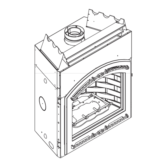
(NOT SHOWN) SECTION 2.E. FIXED GLASS ASSEMBLY (NOT SHOWN) SECTION 14.J. GRATE SECTION 2.B. MANTEL FAN KIT SECTION 2.C HEARTH CLEAR SPACE SECTION 2.D. Figure 2.1 General Operating Parts Heat & Glo • Cerona-36, Cerona-42 • 2106-900 Rev. W • 9/15... -
Page 10: Your Fireplace
Contact your dealer or Hearth & Home Technologies if the barrier is not present or help is needed to properly install one. For more information refer to the instructions supplied with your decorative door or front. Heat & Glo • Cerona-36, Cerona-42 • 2106-900 Rev. W • 9/15... -
Page 11: Lighting Instructions (Ipi)
Keep burner and control compartment clean. See installation and operating instruc- Propane Installation code, CSA B149.1. tions accompanying appliance. For additional information on operating your 593-913i Hearth & Home Technologies fi replace, please refer to www.fi replaces.com. Heat & Glo • Cerona-36, Cerona-42 • 2106-900 Rev. W • 9/15... -
Page 12: After Fireplace Is Lit
Is it normal to see the pilot fl ame burn turned off. Some optional control systems available with IPI models may allow pilot fl ame to continually? remain lit. Heat & Glo • Cerona-36, Cerona-42 • 2106-900 Rev. W • 9/15... -
Page 13: Maintenance And Service
• Carefully set fi xed glass assembly in place on fi replace. Hold glass in place with one hand and secure glass latches with the other hand. • Reinstall door or decorative front. Heat & Glo • Cerona-36, Cerona-42 • 2106-900 Rev. W • 9/15... -
Page 14: Maintenance Tasks-Qualifi Ed Service Technician
• Verify that there is not a short in fl ame sense circuit by checking continuity between pilot hood and fl ame sensing rod. Replace pilot as necessary. Heat & Glo • Cerona-36, Cerona-42 • 2106-900 Rev. W • 9/15... - Page 15 • Cracks compromising the surface plane of the fi rebox. See Figure 3.2. Figure 3.1 IPI Pilot Flame Patterns Figure 3.2. Surface plane of fi rebox is comprised and should be replaced. Heat & Glo • Cerona-36, Cerona-42 • 2106-900 Rev. W • 9/15...
-
Page 16: Installer Guide
FRAMING HEADED OFF IN CEILING JOISTS (SECTION 8.B AND 8.C. ) MANTEL AND MANTEL LEG (SECTION 5.D.) HEARTH EXTENSION (SECTION 5.E.) GAS LINE (SECTION 11.C) Figure 4.1 Typical System Heat & Glo • Cerona-36, Cerona-42 • 2106-900 Rev. W • 9/15... -
Page 17: Design And Installation Considerations
Non-corrosive leak check solution 1/2 - 3/4 in. length, #6 or #8 Self-drilling screws Caulking material (300ºF minimum continuous exposure rating) One 1/4 in. female connection (for optional fan). Heat & Glo • Cerona-36, Cerona-42 • 2106-900 Rev. W • 9/15... -
Page 18: Framing And Clearances
CERONA-36 Inches 42-1/8 73-1/4 65-1/2 22-1/4 Millimeters 1295 1070 1861 1664 CERONA-42 Inches 56-5/8 49-1/8 80-1/8 72-1/2 22-1/4 18-3/4 Millimeters 1438 1248 2035 1842 Figure 5.1 Appliance Locations Heat & Glo • Cerona-36, Cerona-42 • 2106-900 Rev. W • 9/15... -
Page 19: Constructing The Appliance Chase
(Vent Pipe) (Height) (Depth) (Width) of Arch Opening 50-1/2 22-1/4 42-1/8 Cerona-36 1283 1070 1245 54-1/2 22-1/4 49-1/8 45-1/4 Cerona-42 1384 1248 1149 Figure 5.2 Clearances to Combustibles Heat & Glo • Cerona-36, Cerona-42 • 2106-900 Rev. W • 9/15... -
Page 20: Mantel And Wall Projections
mm 25 76 102 127 152 178 203 229 254 279 Figure 5.4 Clearances to Mantel Legs or Wall Projections (Acceptable on both sides of opening.) Heat & Glo • Cerona-36, Cerona-42 • 2106-900 Rev. W • 9/15... -
Page 21: Hearth Extension
fi re- place is raised a minimum of 6 inches above the combus- tible fl oor or hearth. See Figures 5.6, 5.7 and 5.8. Heat & Glo • Cerona-36, Cerona-42 • 2106-900 Rev. W • 9/15... -
Page 22: Termination Locations
Over 16/12 to 18/12 ..........7.0 Over 18/12 to 20/12 ..........7.5 Over 20/12 to 21/12 ..........8.0 * 3 foot minimum in snow regions Figure 6.1 Minimum Height From Roof To Lowest Discharge Opening Heat & Glo • Cerona-36, Cerona-42 • 2106-900 Rev. W • 9/15... - Page 23 2 sides beneath the fl oor. venting system does not meet these requirements. Figure 6.3 Minimum Clearances for Termination • Vinyl protection kits are suggested for use with vinyl siding. Heat & Glo • Cerona-36, Cerona-42 • 2106-900 Rev. W • 9/15...
-
Page 24: Vent Information And Diagrams
DVP6 Effective DVP12 Height/Length DVP24 DVP36 DVP48 1219 DVP6A 3 to 6 76 to 152 DVP12A 3 to 12 76 to 305 Figure 7.2 DVP Pipe Effective Length Heat & Glo • Cerona-36, Cerona-42 • 2106-900 Rev. W • 9/15... -
Page 25: Adding Vent Components
1 inch airspace between the shield and the combustible surface. See Figure 7.6. CORRECT COMBUSTIBLE SURFACE INCORRECT DIRECTION HEAT SHIELD Figure 7.4 Fiberglass Rope Ring 90º ELBOW Figure 7.6 Heat & Glo • Cerona-36, Cerona-42 • 2106-900 Rev. W • 9/15... -
Page 26: Install Support Brackets
If an elbow does not end up in a locked position with the preceding component, attach with a minimum of two (2) sheet metal screws. Heat & Glo • Cerona-36, Cerona-42 • 2106-900 Rev. W • 9/15... - Page 27 Minimal Vertical Vent a minimum verti- Model cal vent before Cerona-36 attaching a 90º e l b o w t o t h e Cerona-42 unit. See chart. Figure 7.8 Heat & Glo • Cerona-36, Cerona-42 • 2106-900 Rev. W • 9/15...
- Page 28 Straight up Vertical Venting Note: On vertical venting confi gurations install the fl ue restrictor found in the appliance manual bag. Follow flue restrictor instructions in Section 9.D. Figure 7.10 Heat & Glo • Cerona-36, Cerona-42 • 2106-900 Rev. W • 9/15...
- Page 29 Model cal vent before Cerona-36 attaching a 90º e l b o w t o t h e Cerona-42 unit. See chart. INSTALLED HORIZONTALLY Figure 7.12 Heat & Glo • Cerona-36, Cerona-42 • 2106-900 Rev. W • 9/15...
-
Page 30: Vent Clearances And Framing
(25.4 mm) above the center of the horizontal vent pipe. Figure 8.1 Horizontal Venting Clearances To Combustible Materials 61-1/2 60-1/2 Cerona-36 1562 1537 Cerona-42 1829 1803 Figure 8.2 Wall Penetration Heat & Glo • Cerona-36, Cerona-42 • 2106-900 Rev. W • 9/15... -
Page 31: Install The Ceiling Firestop
Figure 8.3 Installing Ceiling Firestop INSTALL ATTIC INSULATION SHIELDS BEFORE OR AFTER INSTALLATION OF VENT SYSTEM CEILING FIRESTOP CEILING FIRESTOP INSTALLED BELOW CEILING INSTALLED ABOVE CEILING Figure 8.4 Installing the Attic Shield Heat & Glo • Cerona-36, Cerona-42 • 2106-900 Rev. W • 9/15... -
Page 32: Installing The Optional Heat-Zone
• Heat-Duct: Determine the location of the entry in the air duct system. • Reference the Heat-Zone/Heat-Duct Kit instructions for the remaining installation steps. HEAT-ZONE/HEAT-DUCT KNOCKOUT Figure 8.6 Heat & Glo • Cerona-36, Cerona-42 • 2106-900 Rev. W • 9/15... -
Page 33: Appliance Preparation
Figure 9.1). • Discard brackets. • Replace screws in holes where these pieces were NAILING TABS attached to appliance. Figure 9.2 Proper Positioning, Leveling and Securing of a Appliance Heat & Glo • Cerona-36, Cerona-42 • 2106-900 Rev. W • 9/15... -
Page 34: Installing Non-Combustible Facing Material
• Apply a non-combustible adhesive to attach tile, stone or other non-combustible fi nishing materials per manufacturer’s instructions. APPLY FASTENERS FROM FASTENER PACKET IN SHADED AREAS Figure 9.3 Attaching Non-combustible Facing Material Heat & Glo • Cerona-36, Cerona-42 • 2106-900 Rev. W • 9/15... -
Page 35: Installing Flue Restrictors
EXHAUST FLUE COLLAR RESTRICTOR FIREBOX TOP OF FLAPPER FIREPLACE DOOR EXHAUST PORT EXHAUST FLUE COLLAR RESTRICTOR SCREWS FLAPPER DOOR SCREWS (2) BOTTOM OF FIREPLACE EXHAUST PORT Figure 9.5 Heat & Glo • Cerona-36, Cerona-42 • 2106-900 Rev. W • 9/15... -
Page 36: Installing Vent Pipe (Dvp Pipe)
fl ue at the horizontal elbow joint to prevent the elbow from rotating. Use screws no longer than 1/2 in. (13 mm). If predrilling screw holes, DO NOT penetrate inner pipe. INCORRECT Figure 10.4 Seams Heat & Glo • Cerona-36, Cerona-42 • 2106-900 Rev. W • 9/15... -
Page 37: Assemble Slip Sections
NOTICE: If slip section is too long, the inner and outer fl ues of the slip section can be cut to the desired length. Figure 10.8 Securing Horizontal Pipe Sections Heat & Glo • Cerona-36, Cerona-42 • 2106-900 Rev. W • 9/15... -
Page 38: Disassemble Vent Sections
• Remove shingles or other roof covering as necessary to cut the rectangular hole for the support box. Cut the hole 1/8 in. (3 mm) larger than the support box outline. Heat & Glo • Cerona-36, Cerona-42 • 2106-900 Rev. W • 9/15... -
Page 39: Install Metal Roof Flashing
• Caulk the perimeter of the fl ashing where it contacts the roof surface. See Figure 10.14. • Caulk the overlap seam of any exposed pipe sections that are located above the roof line. Heat & Glo • Cerona-36, Cerona-42 • 2106-900 Rev. W • 9/15... -
Page 40: Install Vertical Termination Cap
• Rest the small leg on the extended heat shield on top of the pipe section to properly space it from the pipe section. Important Notice: Heat shields may not be fi eld constructed. Heat & Glo • Cerona-36, Cerona-42 • 2106-900 Rev. W • 9/15... -
Page 41: Install Horizontal Termination Cap
DVP-TRAP1 can adjust 1-1/2 in. (3-1/8 to 4-5/8) DVP-TRAP2 can adjust 4 in. (5-3/8 to 9-3/8) DVP-HPC1 can adjust 2-1/8 in. (4-1/4 to 6-3/8) DVP-HPC2 can adjust 4-1/8 in. (6-3/8 to 10-1/2) Heat & Glo • Cerona-36, Cerona-42 • 2106-900 Rev. W • 9/15... -
Page 42: Gas Information
fl exible gas connector are connected to the 1/2 in. (13 mm) control valve inlet. • If substituting for these components, please consult local codes for compliance. Heat & Glo • Cerona-36, Cerona-42 • 2106-900 Rev. W • 9/15... -
Page 43: Electrical Information
• Keep wire lengths short as possible by removing any excess wire length. • Low voltage and 110-120 VAC voltage cannot be shared within the same wall box. Heat & Glo • Cerona-36, Cerona-42 • 2106-900 Rev. W • 9/15... - Page 44 FIREPLACE BLACK WHITE box. COPPER GROUND ATTACHED TO GROUND JUNCTION SCREW WITH GROUND WIRE GROUND WIRE INSIDE BOX BOTTOM PAN Figure 12.2 Junction Box Detail Heat & Glo • Cerona-36, Cerona-42 • 2106-900 Rev. W • 9/15...
-
Page 45: Finishing
Cerona-42. The splatter guard must be inserted until tabs are engaged behind arched steel opening for both models. Figure 13.4. Heat & Glo • Cerona-36, Cerona-42 • 2106-900 Rev. W • 9/15... -
Page 46: Mantel Projections
TOP OF ARCH OPENING 32-1/4 16-3/4 16 Cerona-36 406 279 1245 28-1/2 16-3/4 16 11 45-1/4 Cerona-42 406 279 1149 Figure 13.5 Clearances to mantels or other combustibles above appliance Heat & Glo • Cerona-36, Cerona-42 • 2106-900 Rev. W • 9/15... -
Page 47: Facing Material
• See Section 11 for proper clearances. • See Section 1 for combustible/non- combustible defi nitions. 43-5/8 50-3/16 Cerona-36 1108 1275 50-5/8 54-3/8 Cerona-42 1286 1381 Figure 13.7 Non-combustible Facing Material Heat & Glo • Cerona-36, Cerona-42 • 2106-900 Rev. W • 9/15... -
Page 48: Finishing Material Options
Failure to do so will result in the front not fi tting (see Figure holes on the unit to ensure proper placement of the 13.9). door after fi nishing materials are installed. Note: See Section 16.A for decorative front dimensions. Heat & Glo • Cerona-36, Cerona-42 • 2106-900 Rev. W • 9/15... -
Page 49: Hearth Extension
UNDER THE OPENING SURFACE HEARTH EXTENSION FIREPLACE BOTTOM OF Figure 13.14 Fireplace Sitting on Combustible Surface. FIREPLACE Figure 13.12 Fireplace Raised a Minimum of 6 Inches Away from Combustible Surface. Heat & Glo • Cerona-36, Cerona-42 • 2106-900 Rev. W • 9/15... -
Page 50: Appliance Setup
Figure 14.2 Placement of Embers Hearth & Home Technologies-approved optional acces- sories with this appliance. Using non-listed accessories could result in a safety hazard and will void the warranty. Heat & Glo • Cerona-36, Cerona-42 • 2106-900 Rev. W • 9/15... -
Page 51: Positioning The Logs
It may be necessary to tilt Log portion of log #2. #1 forward to properly engage with Log #2. 2106-935B Heat & Glo • Cerona-36, Cerona-42 • 2106-900 Rev. W • 9/15... - Page 52 Figure 8 STEP 6. LOG #6 (SRV2106-706): Rest bottom notch of log #6 on the grate tine and the top part on formed section of log #5 (A). Heat & Glo • Cerona-36, Cerona-42 • 2106-900 Rev. W • 9/15...
- Page 53 Rest the top of the log on the fl at section of log #1. See Figure 3. FORM FITTED FORM FITTED TO GRATE TINE TO GRATE TINE Figure 3 Heat & Glo • Cerona-36, Cerona-42 • 2106-900 Rev. W • 9/15...
- Page 54 Place log #5 on the left side between the grate tine and fi rebox. Note: This log will be used to support log #6. See Figure 6. Figure 6. Heat & Glo • Cerona-36, Cerona-42 • 2106-900 Rev. W • 9/15...
-
Page 55: Fixed Glass Assembly
Replace the glass door on the appliance. Pull out and latch the four glass assembly latches into the groove on the glass frame. LATCHES (BOTH BOTTOM AND TOP) GLASS ASSEMBLY Figure 14.2 Glass Assembly Heat & Glo • Cerona-36, Cerona-42 • 2106-900 Rev. W • 9/15... -
Page 56: Air Shutter Setting
Shutter Settings Burner Cerona-36 Full Open Full Open Cerona-42 Full Open Full Open BOTTOM OF FIREPLACE WITH BOTTOM TRAY REMOVED FIREBOX SUPPORT BASE WING NUT TEMP SENSOR Figure 14.3. Heat & Glo • Cerona-36, Cerona-42 • 2106-900 Rev. W • 9/15... -
Page 57: Troubleshooting
Verify module is securely grounded to metal chassis of appliance. D. Module voltage output / Valve/Pilot Verify battery voltage is at least 2.7 volts. Replace batteries if volt- solenoid ohms readings. age is below 2.7. Heat & Glo • Cerona-36, Cerona-42 • 2106-900 Rev. W • 9/15... - Page 58 ON position. If there is no spark at “I” terminal module must be replaced. If there is a spark at “I” terminal, module is fi ne. Heat & Glo • Cerona-36, Cerona-42 • 2106-900 Rev. W • 9/15...
-
Page 59: Reference Materials
1046 27-3/4 48-1/8 1223 30-1/4 21-3/4 35-7/8 21-3/4 33-7/8 28-1/2 39-1/2 1005 35-3/8 6-5/8 14-1/4 6-3/4 17-3/4 34-1/2 12-1/2 38-5/8 12-5/8 49-7/8 1268 1372 Figure 16.1 Appliance Dimensions Heat & Glo • Cerona-36, Cerona-42 • 2106-900 Rev. W • 9/15... - Page 60 7-1/8 IN. (946mm) (114mm) 1-5/8 IN. (41mm) (180mm) 46 IN. 37-3/4 IN. 1-5/8 IN. (28mm) 1-1/8 IN. (1168mm) (959mm) (40mm) 1-1/8 IN. (28mm) Figure 16.2 Decorative Front Dimensions Heat & Glo • Cerona-36, Cerona-42 • 2106-900 Rev. W • 9/15...
-
Page 61: Vent Components Diagrams
14 in. (356 mm) 5 in. 12 in. (127 mm) (305 mm) 6 in. (152 mm) DVP-HVS (Vent Support) DVP-WS (Wall Shield Firestop) Figure 16.2 DVP vent components Heat & Glo • Cerona-36, Cerona-42 • 2106-900 Rev. W • 9/15... - Page 62 117 mm DVP-TRAP Horizontal Termination Cap 5-3/8 in. 9-3/8 in. Trap2 137 mm 238 mm DVP-TRAP1 DVP-TRAPK1 DVP-TRAP2 DVP-TRAPK2 DVP-HPC1 DVP-HPCK1-B DVP-HPC2 DVP-HPCK2-B Figure 16.3 DVP vent components Heat & Glo • Cerona-36, Cerona-42 • 2106-900 Rev. W • 9/15...
- Page 63 13-7/8 in. 9-1/2 in. 26 in. (352 mm) (241 mm) 660 mm 14 in. (356 mm) DVP-HSM-B Extended Heat Shield DRC-RADIUS Figure 16.4 DVP vent components Cap Shield Heat & Glo • Cerona-36, Cerona-42 • 2106-900 Rev. W • 9/15...
- Page 64 DVP-HPC High Performance Cap 12 in. 305 mm 7-1/4 in. (184 mm) 12-1/2 in. (318 mm) 5-1/4 in. (133 mm) DVP-TVHW VerticalTermination Cap (Highwind) Figure 16.5 Vent Components Heat & Glo • Cerona-36, Cerona-42 • 2106-900 Rev. W • 9/15...
- Page 65 4-3/16 in. 163 mm 106 mm 4-5/8 in. 4 in. 117 mm 102 mm 5-1/16 in. 8-1/8 in. 128 mm 206 mm DVP-2SL Adapter Figure 16.6 Vent Components Heat & Glo • Cerona-36, Cerona-42 • 2106-900 Rev. W • 9/15...
- Page 66 100 FT PV Wire Harness PVI-WH100 separately. Use if the PVLP-SLP is installed in a high traffi c area. PVLP-HS PVLP-BEK Heat Shield Brick Kit Figure 16.7 PVLP-SLP Vent Components Heat & Glo • Cerona-36, Cerona-42 • 2106-900 Rev. W • 9/15...
-
Page 67: Service Parts
Glass Door Assembly GLA-CERONA36 Fan Kit GFK-160A Junction Box 4021-013 2106-025 No longer available Control Box WSK-MLT Post Sn #0021359350 Additional service part numbers appear on following page. 9/15 Heat & Glo • Cerona-36, Cerona-42 • 2106-900 Rev. W • 9/15... - Page 68 Glass Door Assembly Fan Kit GFK-160A Junction Box 4021-013 2106-025 No longer available Control Box WSK-MLT Post SN #0021359354 Additional service part numbers appear on following page. 9/15 Heat & Glo • Cerona-36, Cerona-42 • 2106-900 Rev. W • 9/15...
- Page 69 Ori ce LP (#48) 585-848 Shutter Bracket Assembly (NG) 2106-010 15.14 Shutter Bracket Assembly (LP) 2106-071 15.15 Shutter Sleeve 2026-130 Additional service part numbers appear on following page. Heat & Glo • Cerona-36, Cerona-42 • 2106-900 Rev. W • 9/15...
-
Page 70: Service Parts
LPK-CERONA36 Conversion Kit LP Conversion Kit NG Cerona-42 Conversion Kit LP LPK-CERONA42 Pilot Ori ce NG 593-528 Pilot Ori ce LP 593-527 Regulator NG NGK-DXV Regulator LP LPK-DXV Heat & Glo • Cerona-36, Cerona-42 • 2106-900 Rev. W • 9/15... -
Page 71: Contact Information
5941237, 6006743, 6019099, 6053165, 6145502, 6374822, 6484712, 6601579, 6769426, 6863064, 7077122, 7098269, 7258116, 7470729, 8147240 or other U.S. and foreign patents pending. 2000-945C Printed in U.S.A. - Copyright 2015 Heat & Glo • Cerona-36, Cerona-42 • 2106-900 Rev. W • 9/15...
Need help?
Do you have a question about the CERONA-36 and is the answer not in the manual?
Questions and answers