Table of Contents
Advertisement
Quick Links
Advertisement
Table of Contents

Related Manuals for ClearOne Conferencing Phone


Summary of Contents for ClearOne Conferencing Phone
- Page 1 IP Conferencing Phone ® ’ dministrAtor uide...
- Page 2 MAX IP ADMINISTRATOR’S GUIDE CLEARONE PART NO. 800-158-302 November 2013 (REV. 4.2) © 2013 ClearOne, Inc. All rights reserved. No part of this document may be reproduced in any form or by any means without written permission from ClearOne. ClearOne reserves specific privileges.
-
Page 3: Table Of Contents
able of onTenTs CHAPTER 1: INTRODUCTION .................. 35 eight ............... 35 nvironmental ............... 1 roduct verview : ............... 35 ower ..............1 ervice and uPPort ..........35 adjuSting ower odule Technical Support ..............1 : ................35 etwork Sales and Customer Service ..........1 : ................. -
Page 4: Chapter 1: Introduction
SERVICE AND SUPPORT If you need additional information on how to set up or operate your MAX IP conferencing phone, please contact us. We welcome and encourage your comments so we can continue to improve our products and better meet your needs. -
Page 5: Important Safety Information
IMPORTANT SAFETY INFORMATION Read the safety instructions before first use of this product. This conferencing phone is not designed for making emer- gency telephone calls when the power fails. Make alternative arrangements for access to emergency services. • Read and understand all instructions and follow all warnings marked on the product. -
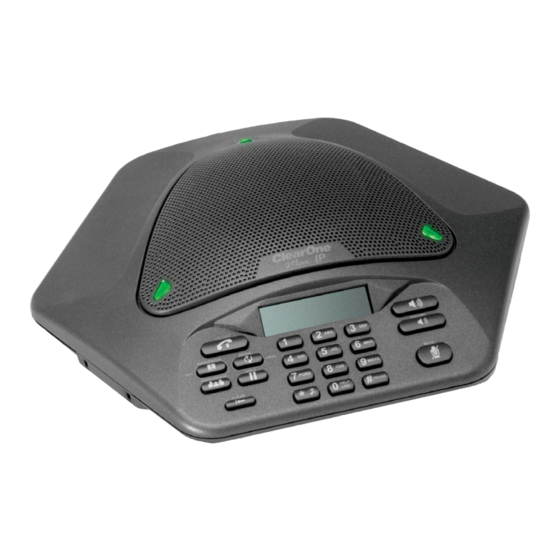
Page 6: Unpacking
Figure 1.1 - MAX IP Parts » NOTE: ClearOne is not responsible for product damage incurred during shipping. Claims must be made directly with the carrier. Inspect your shipment carefully for obvious signs of damage. If the ship- ment appears damaged, retain the original boxes and packing material for inspection by the carrier. -
Page 7: Chapter 2: Getting Started
CHAPTER 2: GETTING STARTED CONNECTING THE CONFERENCING PHONE Connect the Connection cable from the Link Out jack on the base unit to the Link In jack on the conferencing pod (Figure 2.1). Figure 2.1 - Connecting the MAX IP WARNING: DO NOT plug a laptop or PC into the Link Out jack on the base unit or conferencing pod - severe electrical damage can occur if this is done. -
Page 8: Provisioning The Max Ip Phone
PROVISIONING THE MAX IP PHONE There are two methods available for configuring your MAX IP phone: • The first method, called TFTP Provisioning, provisions the phone automatically when it is plugged into the network. This method uses a DHCP server to assign the phone minimal IP information so that it can access the network, including an IP address, gateway, subnet mask, and TFTP server address. -
Page 9: Tftp Provisioning
TFTP P rovisioning AUTOMATICALLY PROVISIONING THE MAX IP PHONE If there are multiple units that to be provisioned with the same settings, the quickest and most seamless way of accom- plishing this is through TFTP provisioning. In fact, the MAX IP phone is factory-configured to automatically provision by downloading the appropriate configuration files from a TFTP server defined by DHCP on bootup. -
Page 10: Configuration: General Settings
<username> - The username for logging into the Web Portal. Default value: admin <password> - The password for logging into the Web Portal. Default value: clearone <helpline_num> - The number dialed when the help line speed dial is called. Default Value: Not set Allowable Characters: [0-9] <allow_reboot_in_call>... - Page 11 <timezone> - The Time Zone in which the phone resides. Default Value: 5 Allowable Parameters: GMT-12:00 (International Date Line West) GMT-11:00 (Midway Island, Samoa) GMT-10:00 (Hawaii) GMT-09:00 (Alaska) GMT-08:00 (Pacific Time(US & Canada), Tijuana) GMT-07:00 (Mountain Time(US & Canada), Arizona, Chihuahua, LaPaz, Mazatlan) GMT-06:00 (Central Time(US &...
-
Page 12: Configuration: Dial Plan
Configuration: Dial Plan For information on configuring a dial plan, see Configuration: Dial Plan screen on page 19. <dialplan> - The filename on the TFTP server containing the Dial Plan file. Default Value: Undefined Allowable Values: ASCII text filename limited by the filename length limit on the TFTP server. Configuration: Network Settings See Configuration: Network Settings details on page 20 for information on how to set these parameters through the Web Portal. -
Page 13: Onfiguration : Sip P Arameters
Configuration: SIP Parameters See Configuraton: SIP Configuration details on pages 21-22 for information on how to set these parameters through the Web Portal. <localnum> - The unique Local Number of the specific phone being configured. Default Value: 0 Allowable Characters: 0 - 9 <localphonename>... - Page 14 <use_sipauth> - Use SIP authentication credentials when registering with the SIP proxy. Primary Proxy: Index=0, Secondary Proxy: Index=1 Default Value: 0 Allowable Range: 0 - Disable 1 - Enable <sip_username> - The user name with which the phone will authenticate with the SIP proxy if <use_sipauth> is enabled.
-
Page 15: Configuration: Audio Parameters
<tls_enable> - Enable TLS. Primary Proxy: Index=0, Secondary Proxy: Index=1 Default Value: 0 Allowable Range: 0 - Disable 1 - Enable <tls_port> - The TLS Port assignment. Primary Proxy: Index=0, Secondary Proxy: Index=1 Default Value: 5061 Allowable Port Range: 0 - 65535 <tls_private_key>... -
Page 16: P Hone B Ook : A Dd , E Dit And D Elete N
1 - Enable VAD <vad_noise_match> - Defines the VAD Noise Matching algorithm. Default Value: Level Allowable Range: None - Disabled Level g711a2 <vad_noise_order> - The VAD Noise Order. Default Value: 5 Allowable Range: 0 - 10 <g711ulaw_priority> - The G.711 ulaw audio codec Priority. Default Value: 255 Allowable Range: 1 (Lowest) to 255 (Highest) <g711Alaw_priority>... -
Page 17: Dial Plan Configuration File
DIAL PLAN CONFIGURATION FILE The Dial Plan Configuration File defines rules for gathering digits when dialing a phone number and also defines the mapping of the gathered digits to a specific target. A sample dial plan is shown below and can be copied and pasted into a text file for use. -
Page 18: Web Portal Provisioning
The Web interface login screen appears (Figure 2.4). Enter the default username “admin” and the default password “clearone” (case insensitive), then click the OK button. Figure 2.4 - MAX IP Web Portal Login Screen The Web Portal appears, displaying the Device Information screen as described in the next section. -
Page 19: Web Portal Screens
WEB PORTAL SCREENS The following sections display each of the screens included in the MAX IP Web Portal and describe all of the settings that can be modified through each of the screens. Device Information Screen The About Device: Device Information screen (Figure 2.5) displays all of the system information for your MAX IP phone. -
Page 20: C Onfiguration : G Eneral S Ettings S
Configuration: General Settings Screen Use the Configuration: General Settings screen (Figure 2.6) to set up Security, Provisioning, the Help line number, and when a Reboot of the phone is allowed. Figure 2.6 - Configuration: General Settings Screen • Security: To change your username and/or password, enter the new username and/or password in the appropriate fields and then click the Apply button. -
Page 21: Configuration: User Preferences Screen
Configuration: User Preferences Screen Use the Configuration: User Preferences (Figure 2.7) screen to enable/disable Automatic Level Control (ALC) and Automatic Gain Control (AGC), to Mute Incoming Ringer, to set Incoming Ringer Melody and to set the Auto Answer feature. Figure 2.7 - Configuration: User Preferences Screen •... -
Page 22: Configuration: Dial Plan Screen
Configuration: Dial Plan Screen Use the Configuration: Dial Plan (Figure 2.8) screen to view your current dial plan and to choose how you want the dial plan for your MAX IP phone loaded. You can choose to load it from a file containing all of the settings you desire or you can select the settings you wish for your MAX IP phone manually through this screen. -
Page 23: Configuration: Network Settings Screen
Configuration: Network Settings Screen Use the Configuration: Network Settings screen (Figure 2.10) to set up your MAX IP phone on the network. Set the Hostname, Domain Name, Static IP Address, Subnet Mask, Default Gateway, Primary DNS IP Address, Secondary DNS IP Address, SNTP Server 1 IP Address, SNTP Server 2 IP Address, VLAN Priority, and VLAN ID from this screen, along with enabling/disabling DHCP and VLAN. -
Page 24: Configuration: Sip Configuration Screen
Configuration: SIP Configuration Screen Use the Configuration: SIP Configuration screen (Figure 2.11) to configure the SIP (Session Initiation Protocol) settings for your MAX IP phone. SIP is a text-based protocol that is based on HTTP and MIME, which makes it suitable and very flexible for integrated voice-data applications. - Page 25 • Phone number: Enter the phone number associated with the MAX IP unit. • Phone name: Enter the name of the MAX IP unit - usually associated with the room or office it’s setup in. • Registration timeout: Enter the value (in seconds) your phone is to refresh its registration to the SIP proxy server. The default value is 3600.
-
Page 26: Configuration: Audio Settings Screen
Configuration: Audio Settings Screen Use the Configuration: Audio Settings screen (Figure 2.12) to configure the Voice Activity Detection (VAD) settings and to prioritize your preferred audio codecs. Figure 2.12 - Configuration: Audio Settings Screen • Enable VAD: Click the check box to enable VAD or uncheck the box to disable it (VAD is enabled by default). Voice activity detection is a software application that allows a data network carrying voice traffic over the internet to detect the absence of audio and conserve bandwidth by preventing the transmission of “silent packets”... -
Page 27: S Creen
• SRTP Settings: Click the check box to enable the various SRTP setting options. » NOTE: The following settings must match the SIP server requirements. To ensure the settings are cor- rect, contact the local IT Administrator to coordinate these settings prior to implementing them. •... -
Page 28: Umber S Creen
Phonebook: Add, Edit and Delete Number Screen Use the Phonebook: Add, Edit and Delete Number screen (Figure 2.14) to add, modify, and delete numbers from your phonebook. Only numeric characters may be entered into the New number field. Figure 2.14 - Phonebook: Add, Edit and Delete Number Screen •... -
Page 29: Iew L Og : D Evice L Og F Ile S Creen
View Log: Device Log File Screen Use the View Log: Device Log File screen (Figure 2.15) to keep record of device log data. You can then download the log for review by clicking the Download button. The log shows the last 8 KB of log data. Click the Update button to get the most recent 8 KB of data. -
Page 30: T Ools : D Iagnostics
Tools: Diagnostics - VoIP Statistics Screen Use the Tools: Diagnostics - VoIP Statistics screen (Figure 2.16) to check the phone state, update firmware, reboot the phone, and restore default settings. Figure 2.16 - Tools: Diagnostics VoIP Statistics Screen • Check Phone State: Click this button to view VoIP statistics, including the number of packets received, the number of packets lost, and the percent packet loss. -
Page 31: Keypad Setup
eyPad eTuP MANUALLY ASSIGNING AN IP ADDRESS If DHCP is disabled, or you wish to assign a static IP address, then perform the following steps: Press and hold the REDIAL/PROG key until the program icon appears on the LCD screen (Figure 2.17). Figure 2.17 - MAX IP Program Icon NOTE: If a key is not pressed within 30 seconds of entering program mode, the MAX IP phone will beep »... -
Page 32: Chapter 3: User Options
CHAPTER 3: USER OPTIONS PROGRAMMING OPTIONS To allow for individual preferences and enhance ease of use, the following features can be programmed: DHCP , host IP , subnet mask, default gateway IP address, ringer melody, VLAN on/off, help line number, and AGC/ALC. You can also restore factory defaults. -
Page 33: Program Default Gateway Ip Address
Program Default Gateway IP Address Press and hold REDIAL/PROG until the Program icon appears on the LCD screen (Figure 3.1). » NOTE: DHCP must be disabled in order to change the subnet mask manually. Press 4 to enter the Default Gateway IP Address menu. The current default gateway IP address is displayed. Press REDIAL/PROG. -
Page 34: Programming Agc And Alc Settings
Programming AGC and ALC Settings Press and hold the REDIAL/PROG key until the Program icon appears on the LCD screen (Figure 3.1). Press and hold the 8 key. The current AGC setting number will be displayed on the LCD screen. Press REDIAL/PROG. -
Page 35: Chapter 4: Maintenance
Make sure cables are securely connected. • The equipment the other party is using is comparable in quality to your MAX IP conferencing phone and is working properly. While the MAX IP works with speakerphones, cell phones, handsets or installed conferencing systems, the quality of the conference will be impacted if the party you are conferencing with has poor quality equipment. -
Page 36: Error Codes
ERROR CODES General Errors (1 - 100) Networking Errors (101 - 150) Memory allocation error DHCP Error Error reading Flash memory Device does not have an assigned IP address Error opening Flash memory VLAN configuration error Error writing to Flash memory Task suspended, reboot phone Provisioning Errors (151 - 200) tExcTask task suspended... - Page 37 ERROR CODES continued... Dial Plan Errors (201 - 300) Invalid SYSCONFIG parameter Invalid or missing string in DIGITMAP line Invalid or missing MIN_DIGITS in DIGITMAP line Invalid or missing MAX_DIGITS in DIGITMAP line Invalid or missing STRIP_FIRST_DIGITS in DIGITMAP line Error creating Address Invalid or missing DIAL_STRING in DIGITMAP line Error creating Destination...
-
Page 38: Chapter 5: Appendix
CHAPTER 5: APPENDIX SPECIFICATIONS Dimensions Record Output: (W x D x H) Connector: Phone Section: 2.5 mm Mono Audio Jack 10.5” x 10.5” x 3” Impedance: (26.7 cm x 26.7 cm x 7.6 cm) < 1kΩ Base Unit: Bandwidth: 4.25” x 5.5” x 2.5” 200Hz –... -
Page 39: Ompliance
Directive is attested by the application of the CE mark on the equipment. Warranty ClearOne Communications, Inc. (Manufacturer) warrants that this product is free of defects in both materials and work- manship. For warranty information and coverage, refer to the ClearOne Website at www.clearone.com.
Need help?
Do you have a question about the Conferencing Phone and is the answer not in the manual?
Questions and answers