Multitech ISI5634UPCI User Manual
Multimodem isi server cards intelligent seiral interface
Hide thumbs
Also See for ISI5634UPCI:
- Quick start manual (66 pages) ,
- User manual (45 pages) ,
- Command reference manual (33 pages)

Related Manuals for Multitech ISI5634UPCI


Summary of Contents for Multitech ISI5634UPCI
- Page 1 ® MultiModem ISI5634UPCI & ISI9234PCIe Server Cards Intelligent Serial Interface User Guide MultiModem ISI Server Cards User Guide...
-
Page 2: Technical Support
Multi-Tech products directly to our technical support team. Get answers to your most complex questions, ranging from implementation, troubleshooting, product configuration, firmware upgrades and much more. To create an account and submit a Support Case on the Portal, visit https://support.multitech.com. www.multitech.com/support.go Knowledge Base and Support Services: The Knowledge Base provides immediate answers to your questions and gives you access to support resolutions for all Multi-Tech products. -
Page 3: Table Of Contents
Chapter 1 – Introduction and Description......................4 ISI Server Cards ............................4 ISI Modems ..............................4 Driver Installation ............................5 ISI Reset Utility............................5 Technical Specifications ..........................5 Chapter 2 – Windows Installation ........................7 Downloading the Windows Drivers ......................7 Using the Windows Installer ........................ -
Page 4: Chapter 1 - Introduction And Description
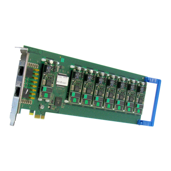
ISI Server Cards The ISI Server Card model ISI5634UPCI uses Universal PCI-bus architecture. The ISI9234PCIe uses PCI Express-bus architecture. The -4 ISI Server card is a server modem expansion card with four V.92 data/Super G3 fax modems. The -8 ISI Server card is an expansion card with eight such modems. These products add modems to communication servers and async hosts that have 32-bit PCI bus architecture. -
Page 5: Driver Installation
Chapter 1 – Introduction and Description digital to analog only once before it reaches your modem. Upstream transmissions and transmissions between client modems are limited to 33.6 Kbps. Upstream transmissions to non-V.92-compatible ISPs and downstream transmissions that are converted more than once on the telephone line are also limited to 33.6K bps. - Page 6 Power: 250 milliamps @ +5vDC (8 ports; ISI5634UPCI-8) 1.75A @3.3v DC (8 ports; ISI5634UPCI-8) 130 milliamps @ +5v DC (4 ports; ISI5634UPCI-4) 885 milliamps @ 3.3v DC (4 ports; ISI5634UPCI-4) 700 milliamps @ 3.3v DC (4 ports; ISI9234PCIE-4) 1.20A @3.3v DC (8 ports; ISI9234PCIE-8)
-
Page 7: Chapter 2 - Windows Installation
If you do not have administrator rights, find someone in your organization with this authorization. Go to http://www.multitech.com/setup/product.go and select your model from the Product drop down list. Click Drivers. Click the link for the Windows drivers. - Page 8 Chapter 2 – Windows Installation Click Continue Anyway each time you are shown the Windows Logo testing window. There will be a transitory screen, then the process will complete. Click on the Finish button. Your driver installation is complete. If you have not already done so, you can now shut down the PC, unplug the power cord and physically install your ISI card per the instructions found in Chapter 3 –...
-
Page 9: Chapter 3 - Hardware Installation
This chapter describes how to install a Multi-Tech ISI as an expansion card in your PCI-bus computer. Telecom Safety Warnings ● This product must be installed by a qualified service person. ● Never install telephone wiring during a lightning storm. ●... -
Page 10: Hardware Installation Procedures
(You may want to save packaging for possible future use.) ISI5634UPCI-8 ISI9234PCIe-8 Remove the slot cover for the unused PCI slot where you will install the ISI Card. Refer to your computer’s manual for instructions on removing the slot cover. - Page 11 Fasten the retaining bracket to the computer chassis and replace cover on the computer. Cable the card. The -4 ISI Server card has one RJ-45 receptacle and one fan-out cable. The -8 ISI Server card has two RJ-45 receptacles and two fan-out cables. Each fan-out cable extends connections for four modems from the RJ-45 plug to four RJ-11 plugs.
-
Page 12: Chapter 4 - Linux Installation
Using Built-in Drivers for Linux Kernel 2.6.8 and Higher Instructions for using the built-in Linux drivers are available in the Multi-Tech Installation Resource website: Go to http://www.multitech.com/setup/product.go and select your model from the Product drop down list. Click Drivers. Click [isi_upci_pcie_linux_26x] to open a text file. -
Page 13: Using Multi-Tech Drivers For Linux Kernel 2.4.X
Making a Driver Installation File Go to http://www.multitech.com/setup/product.go and select your model from the Product drop down list. Click Drivers. Click [isi_upci_linux_104.tar.gz] and save the file to your computer. -
Page 14: Chapter 5 - Configuring The Modems For Your Country
Use the Global Wizard to configure each modem as described below. The Global Wizard configuration utility works with computers running Windows 2000/2003/XP/Vista/2008/7. Installing the Global Wizard Go to http://www.multitech.com/setup/product.go and select your model from the Product drop down list. Click Software. Click Global Wizard link. -
Page 15: Chapter 6 - Reset Utility
Any other utility accessing the first com port needs to be closed before you can access the first com port in the Reset Utility. Go to http://www.multitech.com/setup/product.go and select your model from the Product drop down list. Click Software. Click the Reset Utility link, ISIPortModemReset.exe. -
Page 16: Using The Linux Port Reset Utility
Chapter 6 – Reset Utility If you did not select the first COM port, the following error message displays. Using the Linux Port Reset Utility The port-reset utility allows you to reset ports and modems without rebooting. To reset a serial port, the DTR pin is set to the low logic level for one second. To reset the modem port, the Reset pin is toggled (i.e., its logic state is inverted and then restored). -
Page 17: Appendix A - Cable Wiring Diagrams
The four modems on the ISI-4 are attached to phone receptacles by a single fan-out cable that has an RJ45 connector on one end (which connects to the card) and four RJ11 connectors on the other end (which connect to phone receptacles). -
Page 18: Appendix B - Regulatory Compliance
FCC Part 15 This equipment has been tested and found to comply with the limits for a Class B digital device, pursuant to 47 CFR Part 15 regulations. The stated limits in this regulation are designed to provide reasonable protection against harmful interference in a residential installation. -
Page 19: Appendix C - Environmental Information
Waste Electrical and Electronic Equipment (WEEE) Statement July, 2005 The WEEE directive places an obligation on EU-based manufacturers, distributors, retailers and importers to take- back electronics products at the end of their useful life. A sister Directive, ROHS (Restriction of Hazardous Substances) complements the WEEE Directive by banning the presence of specific hazardous substances in the products at the design phase. -
Page 20: Reach Statement
Appendix C – Environmental Info REACH Statement Registration of Substances: After careful review of the legislation and specifically the definition of an “article” as defined in EC Regulation 1907/2006, Title II, Chapter 1, Article 7.1(a)(b), it is our current view Multi-Tech Systems, Inc. products would be considered as “articles”. -
Page 21: China Rohs
Appendix C – Environmental Info China ROHS 依照中国标准的有毒有害物质信息 根据中华人民共和国信息产业部 (MII) 制定的电子信息产品 (EIP) 标准-中华人民共和国《电子信息产品污染控制管理办法》(第 39 号),也称作中国 RoHS,下表列出了 Multi-Tech Systems Inc. 产品中可能含有的有毒物质 (TS) 或有害物质 (HS) 的名称及含量水平方面的信息。 有害/有毒物质/元素 铅 汞 镉 六价铬 多溴联苯 多溴二苯醚 成分名称 (PB) (Hg) (CR6+) (PBDE) (CD) (PBB) 印刷电路板 电阻器 电容器... -
Page 22: Index
Linux reset utility ............. 16 architecture ................ 4 asynchronous serial devices ..........4 multiplexer channels ............4 cable wiring diagrams ............17 PCI bus variations .............. 4 Country configuration ............14 power ................. 6 drivers REACH statement ............20 Linux 2.4.x ..............13 regulatory compliance .............
Need help?
Do you have a question about the ISI5634UPCI and is the answer not in the manual?
Questions and answers