
Subscribe to Our Youtube Channel
Related Manuals for Grundig GRH-K1004A


Summary of Contents for Grundig GRH-K1004A
- Page 1 Owner's Manual Digital Recording Systems GRH-K1004A 4 Channel H.264 HD-SDI Recorder with DVD-RW Drive GRH-K2108A 8 Channel H.264 HD-SDI Recorder with DVD-RW Drive GRH-K1004A.34.1.01.12.2011 © ASP AG...
-
Page 3: Table Of Contents
2. Monitoring Page 1. Introduction Thank you for purchasing a GRUNDIG digital video recorder for HD-SDI signals. This manual is for GRH-K2108A and GRH-K1004A. Based on the Television Standard for FullHD Television, HDcctv products feature up to 2 Megapixel (1920x1080) pictures in real-time (30fps) transmitted over coax cabling. -
Page 4: Available Versions
Product Warranty and Limits of Responsibility The manufacturer does not assume any responsibility concerning the sale of this product and does not delegate any right to any third party to take any responsibility on its behalf. No warranty is offered for any attachments or parts not supplied by the manufacturer. -
Page 5: Important Safety Instructions
- E-mail and or Twitter notification - Access Live and playback with many Web browsers. Backup with the Internet Explorer - Access Live, playback, search, backup and DVR management with the GRUNDIG Control Center Software - Record, search & playback over a network... -
Page 6: Package Contents
When installing the product, be cautious to locate it in safe places where children cannot reach it. 6. If the product does not operate properly, please contact the closest GRUNDIG distributor for after sales service. Tampering or disassembling the product will cause expiration of the warranty. -
Page 7: Installation
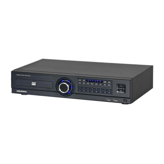
4. Installation 4.1. Part Names and Functions Front view of GRH-K1004A & GRH-K2108A: English... - Page 8 Rear view of GRH-K2108A & GRH-K2108A: English...
- Page 9 Remote Control: It is possible to use all functions of the DVR with the remote control,. If several DVRs are set with unique ID numbers, they can be controlled with one remote control. To use the remote control, it is necessary to set first the ID which you want to use.
-
Page 10: Installation And Connection
DVR will recognise the camera automatically. If you do not get a video, please check the connections first and then make sure the distance is not too far for HDcctv signal: RG59 cable: ca. 100-120m RG6 cable: ca. 200m For bigger distances, please use the GTH-L0011E extender from GRUNDIG. English... - Page 11 Connecting the monitor: Connect a CCTV monitor using either a HDMI cable or a VGA cable with the corresponding port. Connecting Audio: Connect the audio signal to the DVR using the RCA cable or a D-Sub connector as shown below: Supplying Power: Connect the power cable as shown below: English...
-
Page 12: Running The Osd Menu
- When supplying the DVR with power, the DVR starts booting automatically. - In order to cut off the power, press the power switch on the DVR front for 5 seconds. When a pop-up window appears, select “YES” to shut down the DVR. - For supplying the DVR with power again, push the Power button. - Page 13 Dialogue box to edit a word: The dialogue box to edit a word is shown below. It is possible to input both letters and numbers. Keep pressing the [▲/▼], [◀/▶] arrow buttons until the word is typed in, then press [Enter]. In case of deleting press [<--], for spacing press the [-->] button.
- Page 14 Operable range of the remote control: Loading the batteries into the remote control: The remote control requires two AAA-type batteries. Please refer to the following installation steps. 4.3.3. Different configurations Basic configuration: English...
- Page 15 Advanced configuration: English...
- Page 16 Internet/Intranet configuration: 4.3.4. Basic Settings Viewing Image: When powered on, the DVR starts automatically and displays a basic 4 ch-split (GRH-K1004A) or 8-split screen (GRH-K2108A). NOTE: After booting the recorder, by default a prompt for entering the password will appear. The default admin password is: 1234.
- Page 17 Setting Date & Time: - Press the [MENU] button and select “System” when the OSD menu appears. - Select “Date/Time” and press the [Enter] button. Time Zone: (1) Select “Time Zone” using the [◀/▶] or [▲/▼] arrow buttons and press the [Enter] button. (2) Select “Time Zone”...
- Page 18 (1) Select “Apply Date/Time” using the [◀/▶] or [▲/▼] arrow buttons and press [Enter]. Then a warning message will appear as shown below; (2) Select “YES” using the [◀/▶] or [▲/▼] arrow buttons, then press the [Enter] button. To cancel, press the [ESC] button.
- Page 19 Program Setting: Set the resolution, the frame rate and the quality for each channel for normal recording and event recording in the “Program” submenu of the ”Record” menu depending on the model you are using. Schedule Setting: Set the recording mode as “Schedule & Event” and set the date, the time and the program with which you want to record.
-
Page 20: Connecting And Configuring Ports
4.4. Connecting and Configuring Ports 4.4.1. Wire Handling When connecting a wire to a terminal block, follow the instructions below. Note the different types of wire that can be used. - Stranded wire : Peel 8~10 mm of the wiring cover and solder it. Wire gage should be AWG 22~26. - Page 21 Connecting a sensor: Refer to the following images for connecting S1 ~ S8 (S4 for GRH-K1004A). It shows how to connect a dry contact (please also refer to “Wire Handling”). Sensor Settings: (1) Press the [Menu] button and select “Event” when the OSD menu appears.
- Page 22 Specification: In order to run the relay output of the DVR normally, the following conditions are required. Connecting relays: Connect R1~R2 with reference to the following images which show how to connect a warning light. Please also refer to “Wire Handling”. Relay settings: The DVR can activate relays from different events, such as sensor activation, motion detection or the loss of a video signal.
- Page 23 Serial Port Configuration: Configuring serial ports for Pan/Tilt/Zoom cameras: The DVR supports the control of PTZ cameras over the COM port. For a list of supported protocols, please refer to the list on the OSD configuration menu. The following image shows how to connect a PTZ camera to RS485 (COM2/COM3).
- Page 24 The following PTZ protocols are supported by the DVR: Serial Connection Settings: You can set up the serial port and the PTZ configuration in the “Device” menu. English...
- Page 25 Under "Device" > "Serial", you can set the protocol, port, baud rate, parity bit, stop bit and data bit, correspondingly to the settings in the PTZ camera. After completion, switch to "Device" to select a desired channel from the camera menu, and connect the Camera to the corresponding serial port by selecting the PTZ Port under the PTZ menu.
- Page 26 Serial (COM1) Setup: (1) Select “Device” in the OSD menu and move to this sub-menu by pressing [Enter]. (2) Select COM1 and configure the name/type of the device. (3) Set up the value of Baud Rate/Parity/Stop bit/Data bit with the device. Text Setup: (1) Select “Device”...
- Page 27 Connecting USB devices: The USB port can be used for simple video copying (within 1 hour) to an USB memory device. It is recommended to use a device whose specifications are the same as below. NOTE: The USB device has to be formatted with FAT32 to be recognised by the DVR. In the case of normal connection, if executing the Copy menu, the USB device will be automatically recognised as shown below.
- Page 28 Connecting video outputs: If the Video signal is looped through, the DVR notices this and sets the end resistance automatically. Please ensure the correct end resistance setting of the device connected to the video out signal. Connecting audio devices: There are 4 RCA Audio Inputs and 1 RCA Output. English...
- Page 29 4.4.4. HDD Please refer to the following list for compliant HDDs: HDD registration and format: After mounting the HDD and booting the system, the “Disk Manager” will execute automatically. If not, please check the connectivity of the HDD. The Disk Manager can be manually executed in the menu “System” under “Disk”. English...
- Page 30 (3) If you see the message for format, select [Yes]. If the HDD is already correctly formatted, this might not be necessary. (4) Press [ESC] to exit the “Disk Manager”. 4.4.5. Remote monitoring and controlling Using the GRUNDIG Control Center Software, the DVR can be controlled and monitored over an internet/intranet connection. Ethernet connection: (1) Cut the power off.
- Page 31 DDNS: The settings for the GRUNDIG DDNS server are already filled in. You will only need to set the time interval with which the recorder should resend its IP information to the DDNS server. If your firewall and router settings are correct, you should be able to access the DVR now from anywhere in the world by using the following address: [last 6 digits of MAC address].grundig-ddns.eu...
-
Page 32: Menu Use
5. Menu Use 5.1. Menu Structure The menu structure is shown in the image below. The settings for each menu are explained in the following chapters. 5.2. Function Menu To execute the Function menu, click the right button of the mouse or select the ‘FUNC’ button on the front panel. The Function menu can be controlled by mouse or with the direction keys of the front panel. -
Page 33: Factory Reset
From left to right: 1. Access Main Menu 2. Select Multi Mode View 3. Start Sequence 4. Digital Zoom 5. PTZ Control 6. Backup Data 7. Search 8. Enter Playback Mode 9. Key-Lock function (will disable the front panel buttons of the device) 10. - Page 34 FACTORY DEFAULT System: English...
- Page 35 Network: English...
- Page 36 Device: Event: English...
- Page 37 Record: Program initial value for GRH-K1004A / GRH-K2108A: English...
-
Page 38: Monitoring
Press [MULTI] for multi channel display or click the “Display” icon in the Function menu. Every time you press the [MULTI] button, the screen mode will change. For GRH-K1004A you only have the 1-4 channel multiview. For GRH-K2108A you also have the 5-8, 4C & 1~8 multiview. -
Page 39: Sequence Mode
6.5. Sequence Mode By pressing the [SEQ] button a user defined sequence will start switching between single channels and division views after a preconfigured time. 6.5.1. Sequence Mode Settings The settings for the Sequence Function are configured under “Device” > “Monitor” in the OSD Menu. Select “Seq. -
Page 40: Zoom Screen Mode
In the “Monitor” menu you can define an Event Pop-up time. If this is set, the DVR will display only the channels on which an event occurred. For example, when on 3 channels motion was detected, a 4 division screen will be displayed on the screen, including these 3 channels. -
Page 41: Ptz Control
6.9. PTZ Control Connect a PTZ controller to the DVR and set the relevant protocol in the “Serial Setup” menu and the corresponding camera menu, then the PTZ of the camera can be operated while live monitoring is activated. To pan and tilt a PTZ camera, use the direction keys from the DVR’s front panel or the mouse. - Page 42 - Press the button of the desired channel, or select the channel with the mouse. - Press the PTZ button from the front panel or click on the PTZ icon in the Function menu with the mouse. - The PTZ menu (Zoom/Focus, Load Preset, Save Preset) will appear. - Then press the [Enter] button or click on the mouse.
-
Page 43: Playback
7. Playback 7.1. Playback Mode 7.1.1. Playback on Standard monitor (16 / 9 / 4 division) - Please press the [PLAY] button in monitoring mode or click the [PLAY] button in the Function menu with the mouse. - When pressing the [PLAY] button or the [FWD] button, the video plays in forward direction at 1× speed. - When pressing the [REW] button, the video plays backwards at 1×... -
Page 44: Search Mode
7.2. Search Mode The DVR supports 4 different modes to search for video material (Time, Calendar, Event, Thumbnail). Press the [SEAR] button on the front panel or the search icon in the Function menu to access the Search menu. 7.2.1. Time Search Start-REC Time: The date and time of the first recording End-REC Time:... - Page 45 7.2.2. Calendar Search Month: Select the Month and Year to search for. Use the direction keys or the scroll wheel of the mouse to change the month/the year. Date: Select the Date to search for. Use the direction keys or double-click with the mouse to change the day. Hour: Select the time and push the [Enter] button or double- click with the mouse to start the video.
- Page 46 / Down buttons. With the mouse, click and scroll the wheel. Event Channel: Select the channel for the search: - GRH-K2108A: from Ch1 to Ch8 - GRH-K1004A: from Ch1 to Ch4 Event Type: Select the event type for the search. Choose between: ALL, MD, SENSOR, V- LOSS, TEXT...
-
Page 47: Copy
7.2.4. Thumbnail Search Use this search mode to search by thumbnail preview pictures. Select the channel, date and time and the time interval to create 16 thumbnails of the video. Channel: Select the channel and change the value with the direction keys or the mouse wheel. Start Time: Input the date and time for the starting point and change the value using the Up / Down direction keys or the mouse wheel. - Page 48 7.3.1. CD/DVD This is the copy function if you use a recordable CD or a DVD. Please insert the recordable CD or DVD first before you start the backup menu. The CD or DVD will be automatically detected. Type: Select CD/DVD by using the direction keys or the mouse wheel. Channel: In a pop-up window the user can select some or all channels to be backed up.
- Page 49 Storage device to be able to view the RE4 format. You can also open the RE4 file with the GRUNDIG Control Center. Select the channel you want to record and press [Enter] or use the mouse to open the channel selector as shown below.
- Page 50 Select disk: Select the media you want to copy to. Press [Enter] on the Disk list or click the mouse. Start: Starts the backup. Press [Enter] or click the mouse. NOTE: If the backup is interrupted, the backup files will not be playable on a PC. 7.3.3.
-
Page 51: Configuration
8. Configuration 8.1. System Setup Time, Disk and Authority settings and miscellaneous settings can be configured here. 8.1.1. Date/Time The Date and Time setting should be configured prior to any recording. The Time configuration is very important to protect the recording data. Changing the time during recording is not recommended. - Page 52 Custom DST: You can also use a custom DST. Select a fixed day of a week (first Tuesday of March) or the day of a month (24th of March) to select when the switch should happen. You can also define the exact time, when it should happen. This can be used if you want to change the time not in the middle of the night, but maybe on the noon of the next day, so you have enough time to search for any events using the “old”...
- Page 53 Apply: When pushing the “Apply Date/Time” button, you will see the message box shown below. NOTE: Except for the "Date/Time" configuration, all configurations are saved automatically. The “Date/Time” configuration can have a critical effect on the HDD recording file system, therefore the user has to confirm these changes.
- Page 54 NTP Local server IP: Input the IP address of the local NTP server or a DVR that is working in NTP server mode. Interval: Configure the interval of the time synchronisation. 8.1.2. Disk In the “Disk” menu everything regarding the hard disk of the DVR can be configured. Here you can also use the Disk Manager to format HDDs.
- Page 55 - If you select NO, the HDD will not be formatted. NOTE: If the HDD was already used in a GRUNDIG DVR and was formatted correctly, it will be available for recording even if you selected NO. All previously recorded videos will be also available.
- Page 56 Disk Status: In the “Disk Status” menu you can check the temperature and status of the installed HDDs. Mirroring (only GDV-C4416A & GDV-B8832A): In the mirroring option you can activate the RAID function. You can choose between three options. You need to use identical HDDs to activate this option and ensure a flawless working condition.
- Page 57 NOTE: The recording performance of the DVR will be reduced when the mirror function is activated. 8.1.3. User Setup The user setup is only visible for the administrator. Users can only change their passwords here. In the user setup you can define which user has which rights. You can choose that users are only allowed to access defined channels and can only execute defined functions.
- Page 58 Functions: Here you can define which functions of the DVR the user can access. Menu: gives the user the right to access the configuration menu. (He has less rights than the admin but can change almost anything.) PTZ: If set to YES, the user has the right to control PTZ cameras. Relay: If set to YES, the user has the right to activate the relays of the DVR.
- Page 59 NOTE: The password prompt will be visible after the DVR has started and when nobody is logged in. After that, the user that is logged in has access to all the rights defined in user setup. Change the Password: Select Change P/W for the user whose password should be changed. The password input box will be displayed. The password can be set with the direction keys on the front of the DVR or with the mouse in the text input window.
- Page 60 User setup page for users: A user will see a different page than the administrator. He will be only able to change hisits own password: 8.1.4. Utility Configure the name of the DVR, the remote control ID and Language. DVR Alias: Set the name of the DVR.
- Page 61 Language: Select the language you would like to use. Firmware Update: You can update the firmware by a USB Memory device. - Insert a USB memory device including the firmware file to the USB port. - Press the Firmware Update button. - Select [YES] in the pop-up window.
-
Page 62: Network
Factory Reset: Set all configurations back to factory default. NOTE: Only the administrator is allowed to perform a factory reset. System Information: The System information contains 2 pages of information about the system. On the first page you will see all the relevant system information like firmware and model type. - Page 63 IP Address: The IP Address is for connection between the DVR and the Control Center and also for the web connection with the WebViewer (Net Mask and Gateway need to be configured if you want to access the DVR over the Internet.) Net Mask: The Net Mask determines the range of the IP addresses which are available for use.
- Page 64 If the DVR is connected to a Cable modem or a xDSL modem, the IP address will be changed with every connection to ISP. To connect to the DVR over the Internet you need to know this IP address. GRUNDIG supplies a DDN Server that can be used to update the IP address of the DVR.
-
Page 65: Device Setup
This menu is for setting a server address where the DVR can register its dynamic IP address. The DDNS address, on which GRUNDIG is operating now, is: www.grundig-ddns.eu. You can access the DVR now over the internet and the Control Center Software through the following address: [last 6 digits of the MAC address].grundig-ddns.eu... - Page 66 PTZ Setup: In this menu it is possible to carry out an additional configuration for the PTZ Address and the PTZ Port. PTZ Home: Enable or disable the Home function. If the PTZ is not used manually for a certain time, the camera will move back to the preset position.
- Page 67 8.3.2. Monitor Setup Configure all connected monitors. Depending on the model of the DVR and the attached monitor different options are available. Event Pop-Up: If the Event Pop-Up is set, the selected monitor will display only the channels on which an event occurred. For example, when on 3 channels a motion was detected, a 4 division screen will be displayed on the screen, including these 3 channels.
- Page 68 8.3.3. Audio Setup In this menu the user can configure Audio recording, Volume, Synchronisation and Mixing. Audio Channel: Select the channel you want to configure. Audio Recording: Enable or disable the audio recording. If disabled, audio will be transmitted in live view, but will not be recorded. If audio recording is enabled, the recorded audio will also be available in playback mode.
- Page 69 8.3.4. Text Setup Recording: Enable or disable the recording of transmitted texts. Sync Text with: Select the channel which will be synchronised with the text input. Device: Select the type of the Text input device you are using. Choose between VSI-Pro Hydra, Starfinger 007 or manual configuration.
-
Page 70: Event Setup
8.3.5. Serial Setup The DVR has 3 serial ports. One is a RS-232 serial connection and the other 2 ports are serial RS-485 connections. Serial Port: Select which serial port you want to configure. Device: Select the connected device and the protocol that it is using. Interface: Configure which interface the device is using. - Page 71 8.4.1. Event Check Enable or disable the event checking algorithms. You can set up a schedule for the event check if you want to enable the event check only for a certain time frame. In the case of schedule mode, you can set up schedules for different dates and times, as shown in the following screenshot.
- Page 72 8.4.2. Event Actions Configure what action the DVR will perform if an event is detected. Event Action: There are 7 different actions you can choose from: Relay 1 to 4, Buzzer, FTP, E-Mail and Twitter. Action Duration: Select how long an Action Duration will be kept up. Relay and Buzzer can be configured from 5 seconds to 60 seconds.
- Page 73 System Event source: In the system event source menu you can configure which system events are used for event action (Bad block, Disk full, Fan error, Authorisation failure, DDNS registration failure). E-Mail: Here you can set up the sender & receiver E-mail address. E-mail address: Input the E-mail address to get an event alarm to this E-Mail address.
- Page 74 Authentification: Please select here if your SMTP Server needs an authentification. You can also choose if your SMTP Server is using a TLS encryption method. SMTP Server: Enter your SMTP server address, provided by your email address provider. User ID: Enter the username for your email address. Password: Enter your email password.
- Page 75 Twitter setup: 1. Generate PIN This will generate a link to the Twitter website, where you can allow the access of the DVR to your account. NOTE: If you have a valid e-mail account already set up in your DVR, you can send this link directly to your e-mail address, which will make the setup easier.
- Page 76 This menu is to set up the existing sensor input and the type of the sensor. GRH-K2108A has 8 inputs and GRH-K1004A has 4 inputs. The sensors can be set either to Normal Open (N.O.) or to Normal Close (N.C.).
-
Page 77: Recording Setup
8.4.5. Preset Configure which preset is loaded for PTZ cameras when an event is detected. You can select between sensor events, motion detection and text synchronisation. You can configure up to 16 presets per camera. The preset position can be configured in the PTZ single channel view. 8.5. - Page 78 CH (Channel): Displays the channel number. R (Resolution): There are 2 resolutions: 720p & 1020p. F (FPS): FPS means frame per second. The user can select a frame rate from 1 to 30 fps. The max. frame rate can differ according to the configuration.
- Page 79 Continuous & Event Recording: If the DVR is set to Continuous & Event the DVR will record all the time. If an event occurs the recording setting will be changed from continuous to event settings. Schedule & Event Recording: The DVR can record automatically, depending on the programmed schedule. Set the recording mode to Schedule &...
- Page 80 Select the days and the time zones which you want to record. You can also select different programs for different times. - Program: Set the recording program (A~Z) - Time: Set the applicable time Configuration: Select the recording start time and end time in the table by clicking with the mousee or pressing the front panel buttons.
-
Page 81: Grundig Web Viewer
You can monitor the live view or access the recorded data with this program. The GRUNDIG WebViewer is divided into the Login page, the Monitor page, where you can monitor the live video, and the Playback page to access recorded videos. -
Page 82: User Setup
9.3. User Setup To access the GRUNDIG WebViewer, user authority and password can be changed in the DVR or in the Control Center configuration (see the following images). The basic admin password is “1234” and the user password is “1111“ for User 1, “2222” for User 2 etc. The password for User 10 is “0000”. -
Page 83: Available Browser
9.4. Available Browser The GRUNDIG WebViewer is optimised for the Windows Internet Explorer 6.0 or higher. But GRUNDIG also supplies a Java based access to the DVR that can be used with other browsers like Mozilla Firefox, Apple Safari, Google Chrome or the Opera browser. - Page 84 You can change to 1, 4, 9, 13, 16, 25 or 36 divisions by clicking on the number on top of the page. Also, you can change to 1-channel mode by clicking on any of the channel images. Double-click on one of the channels to switch to 1-channel mode. After entering 1-channel mode, a double-click on the screen will return to the previous division of channels.
- Page 85 9.5.6. Using a microphone You can enable or disable the use of a microphone within the GRUNDIG WebViewer. The default setting is Off. If a microphone is activated, the colour of the corresponding icon will change from blue to red.
- Page 86 During video recording, click the Quick Recording button to stop recording and a dialogue box will be opened to store the recorded files. Saved recording files are saved in “*.re4” file format. The .re4 file can be played back by the GRUNDIG Control Center Playback software or the GRUNDIG Mini Player software.
- Page 87 9.5.10. Using PTZ Among the icons on the top of a video in monitoring mode, click ‘PTZ’ to activate the control Pan, Tilt, Zoom, and Focus. If a PTZ camera is connected and already set to PTZ, this button is activated by default. Pan/Tilt Control: To control the PTZ with the mouse, click the right button and select “PTZ”...
-
Page 88: Playback
If you have the user rights to play back video, you can access the Playback screen when pressing the “Go” button on the Monitor screen of the GRUNDIG WebViewer. In the Playback screen you can monitor up to 16 video streams simultaneously and search through a calendar to see recorded video from that date. - Page 89 9.6.2. Image recording You can save a playback image as ‘.bmp’ picture file. Select the channel with the mouse and click the ‘Save’ button. A Save Image dialogue box appears and you can input a memo text or select if the channel name, date and event data should be written unto the file.
- Page 90 9.6.4. Backup You can choose between .re4 (multi-channel) or .avi (single-channel) backup. Select the time, date and channel you want to back up und choose a location to save the file to. If you want to secure the video file you can input a password which has to be verified. 9.6.5.
- Page 91 9.6.8. Searching in the Calendar When a video was recorded on a special date, that day will be coloured in black. When a day is coloured in grey, this means that there was no video recorded on this date. Select the year, month, day and time to play back the video of that date.
-
Page 92: Java Based Web Viewer
9.7. Java based Web Viewer The GRUNDIG DVRs also support a connection based on Java. This technology can be used to get access to the DVR using another browser than the Microsoft Internet Explorer. The user just needs to select “Java” in the WebViewer start page. -
Page 93: Grundig Live Mobile Viewer
10. GRUNDIG Live Mobile Viewer The GRUNDIG Mobile viewer is a viewer service for monitoring video with many different mobile devices. To access the mobile viewer, the user needs a mobile device supporting Wi-Fi or 3G. 10.1. Log-In Page The picture below shows the Mobile viewer log-in page. -
Page 94: Monitoring Page
10.2. Monitoring Page The monitoring page shows the selected channel video and some functions you can use, right below the video display. The functions can be activated by pressing the buttons (touchscreen devices) or pressing the corresponding number on your phone keypad. For the functions, please refer to the description below. - Page 95 Specifications GRH-K1004A Operating System Embedded OS Video Inputs 4 CH HD-SDI, BNC Video Outputs 1 VGA, 1 HDMI Storage Max. Expansion 16TB (intern or eSATA), 64 TB (GDS-R04A) Video Compression H.264, JPEG Recording Resolution FullHD (1920x1080), HD(1280x720) Recording Speed 60fps (FullHD), 120fps (HD)
- Page 96 Motion Detection On/ Off/ Area Setting Event Source Motion, Alarm, Text, Video Loss, System Event Action Pop-Up, Relay, E-Mail, FTP, Network, Buzzer, PTZ Preset Audio Inputs 4 CH, RCA Audio Outputs 1 CH, RCA Alarm Inputs 8 contact input N/O or N/C Alarm Outputs 4 Relay Compliant...
-
Page 97: Ec Declaration Of Conformity
EC Declaration of Conformity GRH-K1004A 4 Channel H.264 HD-SDI Recorder with DVD- RW Drive GRH-K2108A 8 Channel H.264 HD-SDI Recorder with DVD- RW Drive It is hereby certified that the products meet the standards in the following relevant provisions: EC EMC Directive 2004/108/EC...
Need help?
Do you have a question about the GRH-K1004A and is the answer not in the manual?
Questions and answers