
Related Manuals for Grundig GD-RT-AC3004N


Summary of Contents for Grundig GD-RT-AC3004N
- Page 1 User Manual GD-RT-AC3004N GR-RT-AP5016P GD-RT-AC3016N GR-RT-AP5016N GD-RT-AP5004P GR-RT-AT5016N GD-RT-AP5008P grundig-security.com...
-
Page 2: Table Of Contents
Content 1. Introduction ..........................8 1.1 Model Overview ......................8 1.2 Key Features of the DVRs ....................9 1.3 Front Panel ........................14 1.4 IR Remote Control Operations ..................14 1.5 USB Mouse Operation ....................17 1.6 Input Method Description ..................... 19 1.7 Rear Panel ........................ - Page 3 3.3 Channel-Zero Encoding ....................50 3.4 Adjusting the Live View Settings ..................50 3.5 Manual Video Quality Diagnostics ................. 52 PTZ Controls .......................... 54 4.1 Configuring PTZ Settings ....................54 4.2 Setting PTZ Presets, Patrols and Patterns ..............55 4.2.1 Customizing Presets ....................55 4.2.2 Calling Presets ......................
- Page 4 6.1.5 Playing Back by Smart Search ................93 6.1.6 Playing Back by System Logs ................. 96 6.1.7 Playing Back by Sub-Periods ................. 98 6.1.8 Playing Back External File ..................99 6.1.9 Playing Back Pictures .................... 99 6.2 Auxiliary Functions of Playback ................... 101 6.2.1 Playing Back Frame by Frame ................
- Page 5 10.7 Loitering Detection ....................136 10.8 People Gathering Detection ..................136 10.9 Fast Moving Detection ....................136 10.10 Parking Detection ....................137 10.11 Unattended Baggage Detection ................137 10.12 Object Removal Detection ..................137 10.13 Audio Exception Detection ..................138 10.14 Defocus Detection ....................
- Page 6 13.1.2 One-touch Configuration .................. 162 13.1.3 Manually Creating Array ................... 162 13.2 Rebuilding Array ......................163 13.2.1 Automatically Rebuilding Array................. 164 13.2.2 Manually Rebuilding Array ................164 13.3 Deleting Array ......................165 13.4 Checking and Editing the Firmware ................165 HDD Management ......................
- Page 7 16.7 Restoring Default Settings ..................192 Others ..........................194 17.1 Configuring the General Settings ................194 17.2 Configuring the RS-232 Serial Port ................195 17.3 Configuring the DST Settings ..................196 17.4 Configuring More Settings ..................196 17.5 Managing User Accounts ................... 197 17.5.1 Adding a User ....................
-
Page 8: Introduction
1. Introduction Thank you for purchasing a GRUNDIG product. Before installing or connecting the product, please read first the following documents which you can find on the CD Rom in the product package: - Legal Disclaimer - Safety Instructions - Installation Manual for the respective product model Further information about the product like Data Sheets, CE Documents, etc. -
Page 9: Key Features Of The Dvrs
Each channel supports dual-stream. And sub-stream supports up to 1 WD resolution; ‒ The main stream of GD-RT-AC3004N and GD-RT-AC3016N supports up to 3 MP resolutions with 4 video inputs with channel 1 of the device, 8 video inputs with channels 1 and 2, and 16 video inputs with channels 1, 2, 3 and 4;... - Page 10 GD-RT-AP5004P, GD-RT-AP5008P, GD-RT-AP5016P, GD-RT-AP5016N, GD-RT-AT5016N support line crossing detection and intrusion detection of all channels, and 2-ch sudden scene change detection. GD-RT-AC3004N and GD-RT-AC3016N support 4-ch line crossing detection and intrusion detection, and GD-RT-AC3016N also supports 1-ch sudden scene change detection.
- Page 11 ‒ Supports cloud storage; ‒ S.M.A.R.T. and bad sector detection; ‒ HDD sleeping function; ‒ HDD property: redundancy, read-only, read/write (R/W); ‒ HDD group management; ‒ HDD quota management; different capacities can be assigned to different channels. ‒ For GD-RT-AT5016N, hot-swappable HDD supporting the RAID0, RAID1, RAID5, RAID 6 and RAID10 storage schemes, and can be enabled and disabled on your demand.
- Page 12 ‒ Supports pause, fast forward, slow forward, skip forward and skip backward during playback; locating by dragging the mouse on the progress bar; ‒ 4/8/16-ch synchronous playback; ‒ Manual capture, continuous capture of video images and playback of captured pictures. Backup ‒...
- Page 13 Network Functions ‒ Self-adaptive 100M or 1000M network interface; ‒ IPv6 is supported; ‒ TCP/IP protocol, PPPoE, DHCP, DNS, DDNS, NTP, SMTP, NFS, iSCSI, UPnP™ and HTTPS are supported; ‒ Supports access by Guarding Vision. If you enable Guarding Vision, the device will remind you of the internet access risk and ask you to confirm the “Terms of Service”...
-
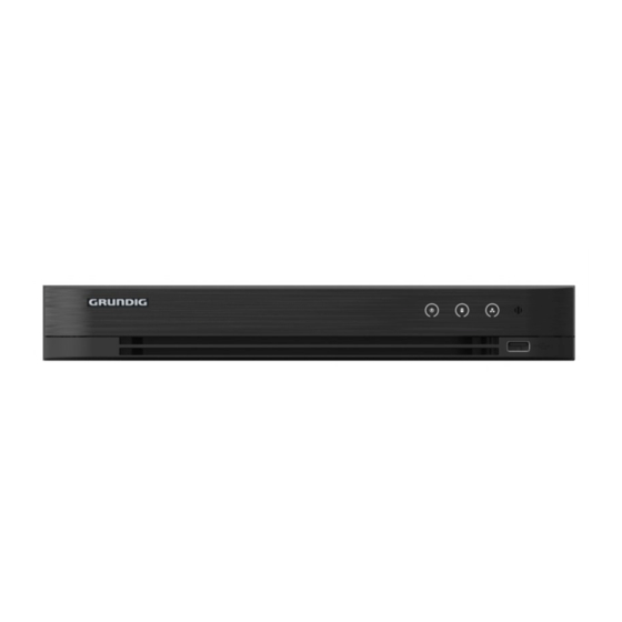
Page 14: Front Panel
1.3 Front Panel Front View: Front Panel of the Other Models Description of the Front Panel of the Other: No. Icon Description Turns white when DVR is powered up. Turns red when data is being read from or written to HDD. - Page 15 Remote Control The keys on the remote control closely resemble the ones found on the front panel. Refer to the table below. They include: Description of the IR Remote Control Buttons: No. Name Description Power on/off the device. POWER Power on/off the device by pressing and holding the button for 5 seconds.
- Page 16 No. Name Description In PTZ control settings, press the button and then you can call a PTZ preset by pressing numeric buttons. It is also used to turn audio on/off in the Playback mode. Navigate between different fields and items in menus. In the Playback mode, the Up and Down button is used to speed up and slow down a recorded video.
-
Page 17: Usb Mouse Operation
No. Name Description It is also used to auto scan in the PTZ Control menu. Switch between single-screen and multi-screen mode. PREV Button In PTZ Control mode, it is used to adjust the focus in conjunction with the A/FOCUS+ button. Troubleshooting the Remote Control: Note: Make sure you have installed the batteries properly in the remote control and that you areaiming... - Page 18 1. Plug the USB mouse into one of the USB interfaces on the front panel of the DVR. 2. The mouse should automatically be detected. In the rare case that the mouse is not detected, the possible reason may be that the two devices are not compatible. Please refer to the recommended device list from your provider.
-
Page 19: Input Method Description
1.6 Input Method Description Soft Keyboard Description of the buttons on the soft keyboard: Description of the Soft Keyboard Icons: Icon Description Icon Description Number English letter … … Lowercase/Uppercase Backspace Switch the keyboard Space Positioning the cursor Enter Symbols Reserved 1.7 Rear Panel Note:... - Page 20 Rear Panel 2: Rear Panel of GD-RT-AC3004N and GD-RT-AC3016N Description of the Rear Panel: Item Description VIDEO IN BNC interface for HD-TVI and analog video input. AUDIO IN RCA connector AUDIO OUT RCA connector. DB15 connector for VGA output. Display local video output and menu.
- Page 21 Rear Panel 3: Rear Panel of GD-RT-AT5016N Description of the GD-RT-AT5016N Rear Panel: No. Item Description VIDEO IN BNC interface for HD-TVI and analog video input. VIDEO OUT BNC connector for video output. AUDIO IN/ RCA connector LOOP OUT (not available) USB Port Universal Serial Bus (USB) port for additional devices.
- Page 22 No. Item Description Power Switch Switch for turning the device on/off. Ground LINE IN BNC connector for audio input. eSATA Connects external SATA HDD, CD/DVD-RW. RS-232 Interface Connector for RS-232 devices. ALARM OUT Connector for alarm output. AUDIO IN RCA connector (not available) 22 ENGLISH...
-
Page 23: Getting Started
2. Getting Started 2.1 Starting Up and Shutting Down the DVR Proper startup and shutdown procedures are crucial to expanding the life of the DVR. Before you start Check that the voltage of the extra power supply is the same with the DVR’s requirement, and the ground connection is working properly. -
Page 24: Activating The Device
For the first-time access, you need to activate the device by setting an admin password. No operation is allowed before activation. You can also activate the device via a web browser, the Grundig Viewer or the an SCMS Client Software. Steps: 1. -
Page 25: Using The Unlock Pattern For Login
Attention 4. (Optional) Click <Yes> to export the GUID. The Reset Password interface pops up. Click <Export> to export the GUID to the USB flash drive for password resetting. Export GUID 5. After exporting the GUID, an Attention box pops up. Click <Yes> to duplicate the password or <No>... - Page 26 Setting the Unlock Pattern Steps: 1. Use the mouse to draw a pattern among the 9 dots on the screen. Release the mouse when the pattern is done. Draw the Pattern Note: ‒ Connect at least 4 dots to draw the pattern. ‒...
-
Page 27: Logging In Via Unlock Pattern
Confirm the Pattern Note: If the two patterns are different, you must set the pattern again. Reset the Pattern 2.3.2 Logging in via Unlock Pattern Note: ‒ Only the admin user has the permission to unlock the device. ‒ Please configure the pattern first before unlocking. Please refer to Chapter 2.3.1 Configuring the Unlock Pattern. - Page 28 Draw the Unlock Pattern 2. Draw the pre-defined pattern to unlock and enter the menu operation. Note: ‒ You can right click the mouse to log in via the normal mode. ‒ If you have forgotten your pattern, you can select the <Forget My Pattern> or the <Switch User>...
-
Page 29: Basic Configuration With The Startup Wizard
2.4 Basic Configuration with the Startup Wizard By default, the <Setup Wizard> starts once the device has loaded. You can follow it to complete the basic configuration. Selecting the language: Steps: 1. Select the language from the drop-down list. 2. Click <Apply> button. Language Configuration Operating the Setup Wizard: Steps:... - Page 30 Start Wizard Interface Click the <Next> button to enter the <Change the Password> interface. 1) Enter the <Admin Password>. 2) (Optional) Check the checkbox of <New Admin Password>, enter the <New Password> and confirm it. 3) (Optional) Check the checkbox of <Enable Pattern Unlock> and draw the unlock pattern.
- Page 31 After the time settings, click the <Next> button to enter the <General Network Setup Wizard> interface as shown below. General Network Configuration Click the <Next> button after you configured the basic network parameters. Click the <Next> button to enter the <Advanced Network Parameters> interface. You can <enable DDNS>...
- Page 32 HDD Management To initialize the HDD, click the <Init> button. Initialization will remove all the data saved in the HDD. Click the <Next> button to enter the <IP Camera Management> interface. Add the IP camera. 1) Click <Search> to search the online IP Camera. The <Security> status shows whether it is active or inactive.
-
Page 33: Login And Logout
IP Camera Management After completing the IP Camera settings, click <Next> to enter the <Record Settings> interface. Click , and you can enable the continuous recording or motion detection recording for all channels of the device. Record Settings Click <OK> to complete the wizard settings. 2.5 Login and Logout 2.5.1 User Login You have to log in to the device before operating the menu and other functions. -
Page 34: User Logout
Login Interface 2. Enter the <Password>. 3. Click <OK> to log in. Note: In the Login interface, for the admin user, if you have entered the wrong password 7 times, the account will be locked for 60 seconds. For the operator, if you have entered the wrong password 5 times, the account will be locked for 60 seconds. -
Page 35: Resetting Your Password
2.6 Resetting Your Password When you forget the password of the admin user, you can reset the password by importing the GUID file. The GUID file must be exported and saved in the local USB flash drive after you have activated the device (refer to Chapter 2.2 Activating the Device). - Page 36 Steps: 1. Select <Add IP Camera> from the right-click menu in live view mode or go to Menu> Camera> IP Camera. For the IP cameras detected online in the same network segment, the <Security> status shows whether it is active or inactive. IP Camera Management Interface 2.
-
Page 37: Adding The Online Ip Camera
Set New Password WARNING: STRONG PASSWORD RECOMMENDED-We highly recommend you create a strong password of your own choosing (Using a minimum of 8 characters, including at least three of the following categories: upper case letters, lower case letters, numbers, and special characters.) in order to increase the security of your product. - Page 38 IP Camera Management Interface 2. The online cameras with same network segment will be detected and displayed in the camera list. 3. Select the IP camera from the list and click to add the camera (with the same admin password of the DVR’s). Or you can click the <One-touch Adding> button to add all cameras (with the same admin password) from the list.
- Page 39 OPTION 2: Steps: 1. On the <IP Camera Management> interface, click the <Custom Adding> button to pop up the <Add IP Camera (Custom)> interface. Custom Adding IP Camera Interface 2. You can edit the IP address, protocol, management port and other information of the IP camera to be added.
- Page 40 Successfully Added IP Cameras Please refer to Chapter 18.1 Fehler! Verweisquelle konnte nicht gefunden werden. for the number of connectable IP cameras for different models. Explanation of the Icons: Icon Explanation Icon Explanation Edit basic parameters of Add the detected IP camera. the camera The camera is disconnected;...
-
Page 41: Editing The Connected Ip Camera
2.7.3 Editing the Connected IP Camera After adding the IP cameras, the basic information of the cameras is listed on the interface, and you can configure the basic settings of the IP cameras. Steps: 1. Click the icon to edit the parameters. You can edit the <IP address>, <Protocol> and other parameters. -
Page 42: Connecting Poc Cameras
Password Configuration of the Camera 5. Click <OK> to save the settings and exit the interface. 2.8 Connecting PoC Cameras GD-RT-AP5004P, GD-RT-AP5008P and GD-RT-AP5016P support PoC (Power over Coaxitron) camera connections. The DVR will detect the connected PoC cameras automatically, manage the power consumption via the coaxial communication, and provide power to the cameras via coaxitron. -
Page 43: Configuring The Signal Input Channel
2.9 Configuring the Signal Input Channel Note: This chapter is only applicable to GD-RT-AT5016N. You can configure the analog and IP signal input types and enable 5 MP long distance transmission. Steps: 1. Go to Menu > Camera > Signal Input Status. 2. -
Page 44: Live View
3. Live View 3.1 Introduction of Live View Live view shows you the video image captured by each camera in real time. The DVR will automatically enter Live View mode when powered on. It is also at the very top of the menu hierarchy, thus hitting the ESC many times (depending on which menu you’re on) will bring you to the Live View mode. -
Page 45: Using The Mouse In Live View
‒ <Playback>: play back the recorded videos for the current day. ‒ <Aux/Main Monitor>: the DVR checks the connection of the output interfaces to define the main and auxiliary output interfaces. When the aux output is enabled, the main output cannot do any operation, and you can do some basic operation on the live view mode for the Aux output. - Page 46 Multi-Screen Adjust the screen layout by selecting from the drop-down list. Previous Switch to the previous screen. Screen Next Screen Switch to the next screen. Start/Stop Enable/disable the auto-switch of the screens. Auto-Switch Note: The dwell time of the live view configuration must be set before using <Start Auto-Switch>.
-
Page 47: Switching Main/Aux Output
Right-click Menu 3.2.2 Switching Main/Aux Output Note: ‒ Refer to Chapter 3.2 Operations in Live View Mode for the main and aux output relationship. ‒ The CVBS output only serves as the aux output or live view output. Steps: 1. Use the mouse wheel to double-click on the <HDMI1/VGA>, or <HDMI2>, or <HDMI/VGA> output screen, and a message will box pop up. - Page 48 Quick Setting Toolbar You can refer to the table below for the description of the Quick Setting Toolbar icons. Description of Quick Setting Toolbar Icons: Icons Description Icons Description Icons Description Enable/Disable Instant Playback Mute/Audio on Manual Record PTZ Control Digital Zoom Image Settings Close Live View...
- Page 49 Note: You can configure face detection only when it is supported by the connected camera. Move the mouse onto the Information icon to show the real-time stream information, including the frame rate, bit rate, resolution and stream type. Information Note: When an H.264 IP camera is connected, the stream type is displayed as H.264.
-
Page 50: Channel-Zero Encoding
3.3 Channel-Zero Encoding Sometimes you need to get a remote view of many channels in real time from the web browser or the SCMS (Client Management System) software, in order to decrease the bandwidth requirement without affecting the image quality. Channel-zero encoding is supported as an option for you. Steps: 1. - Page 51 Live View-General The settings available in this menu include: ‒ <Video Output Interface>: Selects the output to configure the settings. ‒ For GD-RT-AT5016N, you can select <VGA/HDMI1>, <HDMI2>, <Main CVBS> for the <Video Output Interface>. ‒ For other models, you can select <Main CVBS> and <HDMI/VGA> for the <Video Output Interface>.
-
Page 52: Manual Video Quality Diagnostics
Live View-Camera Order 2) Click a window to select it, and then double-click a camera name in the camera list you would like to display. Setting an <X> means the window will not display any camera. 3) You can also click to start the live view of all channels in order and click to stop the live view of all channels. - Page 53 Video Quality Diagnostics 2. Check the checkboxes to select the channels for diagnostics. 3. Click the <Diagnose> button and the results will be displayed on a list. You can view the video status and diagnostics time of the selected channels. Diagnostics Result Note: ‒...
-
Page 54: Ptz Controls
4. PTZ Controls 4.1 Configuring PTZ Settings Follow the procedure to set the parameters for PTZ. The configuring of the PTZ parameters should be done before you control the PTZ camera. Steps: 1. Go to Menu >Camera> PTZ. PTZ Settings 2. -
Page 55: Setting Ptz Presets, Patrols And Patterns
Note: ‒ All the parameters should be exactly the same as the PTZ camera parameters. ‒ For the connected Coaxitron camera/dome, you can select the PTZ protocol to UTC (Coaxitron). Make sure the protocol selected here is supported by the connected camera/dome. ‒... -
Page 56: Calling Presets
Steps: 1. Go to Menu>Camera>PTZ. PTZ Settings 2. Use the directional button to wheel the camera to the location where you want to set the preset; the zoom and focus operations can be recorded in the preset as well. 3. Enter the preset No. (1~255) in the <Preset> text field, and click the <Set> button to link the location to the preset. -
Page 57: Customizing Patrols
PTZ Panel-General 4. Click to enter the preset No. in the corresponding text field. 5. Click the <Call Preset> button to call it. Note: When the Coaxitron camera/dome connected and the PTZ protocol is selected to UTC (Coaxitron), you can call the preset 95 to enter the menu of the connected Coaxitron camera/dome. Use the directional buttons on the PTZ control panel to operate the menu. -
Page 58: Calling Patrols
3. Click the <Set> button to add key points for the patrol. Key point Configuration 4. Configure key point parameters, such as the key point No., the duration of staying for one key point and the speed of patrol. The key point is corresponding to the preset. The <Key Point No.>... -
Page 59: Customizing Patterns
3. Select a patrol in the drop-down list and click the <Call Patrol> button to call it. 4. You can click the <Stop Patrol> button to stop calling it. 4.2.5 Customizing Patterns Patterns can be set by recording the movement of the PTZ. You can call the pattern to make the PTZ movement according to the predefined path. -
Page 60: Customizing Linear Scan Limit
PTZ Panel - General 3. Click the <Call Pattern> button to call it. 4. Click the <Stop Pattern> button to stop calling it. 4.2.7 Customizing Linear Scan Limit The Linear Scan can be enabled to trigger the scan in the horizantal direction in the predefined range. -
Page 61: Calling Linear Scan
Note: The speed dome starts a linear scan from the left limit to the right limit, and you must set the left limit on the left side of the right limit. Also, the angle from the left limit to the right limit should be no more than 180º. -
Page 62: Ptz Control Panel
PTZ Panel - One-touch 3. There are 3 one-touch park types selectable. Click the corresponding button to activate the park action. <Park (Quick Patrol)>: The dome starts to patrol from the predefined preset 1 to preset 32 in order after the park time. The undefined preset will be skipped. <Park (Patrol 1)>: The dome starts moving according to the predefined <Patrol 1>... - Page 63 Note: In the PTZ control mode, the PTZ panel will be displayed when a mouse is connected with the device. If no mouse is connected, the icon appears in the lower-left corner of the window, indicating that this camera is in PTZ control mode. PTZ Control Panel You can refer to the table below for the description of the PTZ panel icons.
-
Page 64: Recording And Capture Settings
5. Recording and Capture Settings Note: The picture capture is supported by the GD-RT-AT5016N only. 5.1 Configuring the Encoding Parameters Before you start 1. Make sure that the HDD has already been installed. If not, please install an HDD and initialize it. (Menu>HDD>General) HDD- General 2. - Page 65 GD-RT-AP5004P, GD-RT-AP5008P, GD-RT-AP5016N, GD-RT-AT5016N support 5 MP and 4 MP resolutions on all of the channels. ‒ The 3 MP signal input is available for channel 1 of GD-RT-AC3004N, and for channel 1/2/3/4 of GD-RT-AC3016N. ‒ The analog signal inputs (HD-TVI, AHD, HDCVI, CVBS) and the IP signal input can be recognized and connected automatically.
- Page 66 <Frame Rate>: Set the frame rate for the recording. Note: ‒ For GD-RT-AC3004N and GD-RT-AC3016N, when the 3 MP signal input is connected, the frame rate of the main stream cannot exceed 15 fps. ‒ For GD-RT-AP5004P, GD-RT-AP5008P, GD-RT-AP5016N, GD-RT-AT5016N, when the 5 MP signal input is connected, the frame rate of the main stream cannot exceed 12 fps.
- Page 67 ‒ After enabling H.264+ or H.265+, the <Bitrate Type>, <Video Quality>, <Max. <Bitrate Mode>, <Max. Bitrate(Kbps) > and <Max. Bitrate Range Recommend> are not configurable. ‒ If H.265+ is enabled, the line crossing detection and the region entrance detection are not supported.
- Page 68 ‒ Redundant HDD is required for the redundant record function. For detailed information, see Chapter 14.3.2 Setting HDD Property. ‒ For network cameras, the parameters of Main Stream (Event) are not editable. 5. Click <Apply> to save the settings. 6. Optionally, you can click <Copy> to copy the settings to other analog channels, if needed. Copy Camera Settings 7.
-
Page 69: Configuring The Recording And Capture Schedule
‒ The minimum frame rate for the sub-stream is 1 fps. ‒ You can select the <Video Encoding> for the sub-stream of IP and analog cameras. For the analog cameras, <H.264> and <H.265> are selectable. For the IP cameras supporting H.265, you can select <H.265>... - Page 70 Record Schedule Different recording types are marked in different color icons. <Continuous>: scheduled recording. <Event>: recording triggered by all event triggered alarms. <Motion>: recording triggered by motion detection. <Alarm>: recording triggered by alarm. <M/A>: recording triggered by either motion detection or alarm. <M&A>: recording triggered by motion detection and alarm.
- Page 71 Edit Schedule- All Day 4) To arrange another schedule, leave the <All Day> checkbox blank and set the Start/End time. Edit Schedule- Set Time Period Note: ‒ Up to 8 periods can be configured for each day. The time periods cannot be overlapped with each other.
-
Page 72: Configuring The Motion Detection Recording And Capture
Note: The <Holiday> option is available when you enable a holiday schedule in <Holiday Settings>. See Chapter 5.7 Configuring Holiday Record. 6) Click <OK> to save the settings and to return to the upper level menu. Draw the schedule 1) Click the color icon to select a record type in the event list on the right-side of the interface. - Page 73 Motion Detection 2. Configure Motion Detection: 1) Choose the camera that you want to configure. 2) Check the checkbox for <Enable Motion Detection>. 3) Drag and draw the area for the motion detection with the mouse. If you want to set the motion detection for all of the area captured by the camera, click <Full Screen>.
-
Page 74: Configuring The Alarm Triggered Recording And Capture
Motion Detection Settings 5) Select the channels which you want the motion detection event to trigger for the recording. 6) Click <Apply> to save the settings. 7) Click <OK> to go back to the upper level menu. 8) Exit the <Motion Detection> menu. 3. -
Page 75: Configuring The Event Recording And Capture
5. Check the checkbox of <Enable> to enable alarm. Click the button after <Settings> to set the triggered channels, arming schedule, linkage actions and PTZ linking. Refer to step 4 of Chapter 5.2 Configuring the Recording and Capture Schedule for detailed operations. Alarm Handling 7. - Page 76 2-ch sudden scene change detection. Channels with audio support audio exception detection. ‒ GD-RT-AC3004N and GD-RT-AC3016N support 4-ch line crossing detection and intrusion detection. GD-RT-AC3016N also support 1-ch sudden scene change detection. Channels with audio support audio exception detection.
-
Page 77: Configuring The Manual Recording And Continous Capture
Set Triggered Camera of VCA Alarm 6. Enter the <Record Schedule Settings> interface (Menu> Record> Schedule>Record Schedule), and then set Event as the record type. For details, see step 2 in Chapter 5.2 Configuring Recording and Capture Schedule. 5.6 Configuring the Manual Recording and Continous Capture Follow the steps to set parameters for the manual recording and continuous capture. -
Page 78: Configuring The Holiday Recording And Capture
3. Disable manual record. Click the status icon to change it to Or click the status icon of <Analog> to disable manual record of all channels. Note: After rebooting, all the enabled manual records are canceled. 5.7 Configuring the Holiday Recording and Capture Follow the steps to configure the record or capture schedule on holiday for that year. - Page 79 Edit Holiday Settings 2) Check the checkbox of <Enable>. 3) Select the <Mode> from the drop-down list. There are three different modes for the date format to configure a holiday schedule. <By Month>, <By Week>, and <By Date> are selectable. 4) Set the start and end date.
-
Page 80: Configuring The Redundant Recording And Capture
5.8 Configuring the Redundant Recording and Capture Enabling redundant recording and capture, which means saving the record files and captured pictures not only in the R/W HDD but also in the redundant HDD, will effectively enhance the data safety and reliability. Before you start You must set the Storage mode in the HDD advanced settings to <Group>... -
Page 81: Configuring The Hdd Group
3) Click <OK> to go back to the upper level menu. 3. Go to Menu > Record > Parameters > Record. 1) Select the camera you want to configure. 2) Click the <More Settings> button. More Settings 3) Check the checkbox for <Redundant Record>. 4) Click <OK>... -
Page 82: Files Protection
5. Choose the Channels in which you want to save the record files in the HDD group. 1) Go to Menu > HDD > Advanced > Storage Mode. HDD Advanced 2) Choose a Group number in the drop-down list of <Record on HDD Group> 3) Check the channels you want to save in this group. - Page 83 Export 2. Select the channels you want to investigate by changing the checkbox to 3. Configure the <record mode>, <record type>, <file type>, <start time> and <end time>. 4. Click <Search> to show the results. Export-Search Result 5. Protect the record files. 1) Find the record files you want to protect, and then click the icon which will turn to , indicating that the file is locked.
- Page 84 Steps: 1. Go to Menu > HDD > General. HDD General 2. Click to edit the HDD you want to protect. HDD General- Editing 3. Set the HDD to <Read-only>. 4. Click <OK> to save the settings and go back to the upper level menu. Note: ‒...
-
Page 85: One-Key Enabling And Disabling H.264+/H.265+ For Analog Cameras
5.11 One-Key Enabling and Disabling H.264+/H.265+ for Analog Cameras You can one-key enable or disable H.264+/H.265+ for the analog cameras. Task 1: One-Key Enabling H.264+/H.265+ for All Analog Cameras Steps: Go to Menu > Record > Advanced. Advanced Settings 2. Click <Enable> to enable H.264+/H.265+ for all the analog cameras and the following attention box pops up. -
Page 86: Configuring 1080P Lite
When the 1080P Lite Mode is enabled, the encoding resolution at 1080P Lite (real-time) is supported. If not, up to 1080P (non-real-time) is supported. Note: This chapter is appplicable to GD-RT-AC3004N and GD-RT-AC3016N. Task 1: Enabling the 1080P Lite Mode Steps: Go to Menu >... -
Page 87: Playback
6. Playback 6.1 Playing Back Record Files 6.1.1 Instant Playback Play back the recorded video files of a specific channel in the live view mode. Channel switch is supported. Instant playback by channel Choose a channel in the live view mode and click the button in the quick settings toolbar. - Page 88 Right-click Menu under the Live View Playback by Time Play back video files recorded in a specified time frame. Multi-channel simultaneous playback and channel switch are supported. Steps: 1. Go to Menu > Playback. 2. Check the checkbox of channel(s) in the channel list and then double-click to select a date on the calendar.
- Page 89 Playback Interface Select the channel(s) if you want to switch playback to another channel or execute simultaneous playback of multiple channels. Toolbar of Playback Detailed Explanation of the Playback Toolbar: Button Operation Button Operation Button Operation Audio Start/Stop Lock File on/Mute clipping File...
-
Page 90: Playing Back By Event Search
Button Operation Button Operation Button Operation 30s forward 30s reverse Pause/Play Fast forward Previous day Slow forward Full Screen Exit Next day Scaling Save the clips Process bar up/down the time line Enable/Disable Capture POS information Picture overlay Note: ‒ indicates the start time and the end time of the record files. - Page 91 Video Search by Motion Detection 4. Click <Search> and the record files matching the search conditions will be displayed on a list. 5. Select and click this button to play back the record files. You can click the <Back> button to return to the search interface. If there is only one channel triggered, clicking this button takes you to the <Full-screen Playback>...
-
Page 92: Playing Back By Tag
7. You can click to select the previous or the next event. Please refer to the table in section 6.1.5 for the description of the buttons on the toolbar. 6.1.4 Playing Back by Tag A video tag allows you to record related information like people and location of a certain time point during the playback. -
Page 93: Playing Back By Smart Search
Tag Management Interface Steps 1. Select <Tag> from the drop-down list in the <Playback> interface. 2. Choose channels, edit the start time and the end time, and then click <Search> to enter the <Search Result> interface. Note: You can enter a keyword in the textbox to search the tag on your command. - Page 94 1. Log in the IP camera via the web browser and enable the intrusion detection by checking the checkbox of it. You may enter the motion detection configuration interface via Configuration > Advanced Configuration > Events > Intrusion Detection. Setting Intrusion Detection on IP Camera 2.
- Page 95 detection Set full screen for Start/Stop Clear all motion detection clipping File management Pause playing Stop playing for video clips /Play Filter video files Search matched Smart settings by setting the video files target characters Show/Hide VCA information 5. Set the rules and areas for the smart search for a VCA or motion event. ‒...
-
Page 96: Playing Back By System Logs
Set Result Filter Note: The Result Filter function is supported by the IP camera only. 9. (Optional) For the cameras supporting VCA, click to show the VCA information. Then the configured line or quadrilateral in the VCA configuration and the target frame(s) will be shown on the playback interface. - Page 97 System Log Search Interface 2. Set search time and type and click the <Search> button. Result of System Log Search 3. Choose a log with a record file and click to enter the <Playback> interface. Note: If there is no record file at the point in time of the log, the message box “No result found” will pop up.
-
Page 98: Playing Back By Sub-Periods
Interface of Playback by Log 6.1.7 Playing Back by Sub-Periods The video files can be played simultaneously in multiple sub-periods on the screens. Steps: 1. Go to Menu > Playback. 2. Select <Sub-periods> from the drop-down list in the upper-left corner of the page to enter the <Sub-periods Playback>... -
Page 99: Playing Back External File
22:00 and the 6-screen display mode is selected, then it can play the video files simultaneously for 1 hour on each screen. 6.1.8 Playing Back External File Perform the following steps to look up and play back files in the external devices. Steps: 1. - Page 100 Check the checkbox to select the channel(s) and specify the start time and end time for the search. Click <Search> to enter the <Search Result> interface. Note: Up to 4000 pictures can be displayed at one time. Choose a picture you want to view and click You can click <Back>...
-
Page 101: Auxiliary Functions Of Playback
6.2 Auxiliary Functions of Playback 6.2.1 Playing Back Frame by Frame Play video files frame by frame in order to check image details of the video when abnormal events happen. Steps: 1. Go to the <Playback> interface and click until the speed changes to Single frame. 2. -
Page 102: File Management
2. Check more than one checkboxes to select multiple channels and click to select a date on the calendar. 3. Click to play back the record files reversely. 6.2.4 File Management You can manage the video clips, captured pictures in playback, locked files and tags you have added in the playback mode. -
Page 103: Backup
7. Backup 7.1 Backing up Record Files Before you start Please insert the backup device(s) into the device. 7.1.1 Backing up by Normal Video/Picture Search The record files or pictures can be backed up to various devices, such as USB devices (USB flash drives, USB HDDs, USB writer), a SATA writer and an e-SATA HDD. - Page 104 Result of Normal Video Search for Backup 5. Select video files to export from the <Chart> or the <List> and click the button <Export> to enter the <Export> interface. You can also click <Export All> to select all of the video files for the backup and enter the <Export>...
-
Page 105: Backing Up By Event Search
9. A prompt message will pop up after the backup process is complete. Click <OK> to confirm. Export Finished Note: The backup of pictures using a USB writer or a SATA writer has the same operating instructions. Please refer to the steps described above. 7.1.2 Backing up by Event Search Back up event-related record files using USB devices (USB flash drives, USB HDDs, USB writer), a SATA writer or an eSATA HDD. -
Page 106: Backing Up Video Clips
Result of Event Search 6. Export the video files. Please refer to step 5 of Chapter 7.1.1 Backing up by Normal Video/Picture Search for details. 7.1.3 Backing up Video Clips You may also select video clips in the playback mode to export them directly during the playback, using USB devices (USB flash drives, USB HDDs, USB writer) or a SATA writer. -
Page 107: Managing Backup Devices
4. Export the video clips during playback. Please refer to step 5 of Chapter 7.1.1 Backing up by Normal Video/Picture Search for details. 7.2 Managing Backup Devices Management of USB flash drives, USB HDDs and eSATA HDDs Steps: 1. Enter the <Export> interface. Storage Device Management 2. -
Page 108: Alarm Settings
8. Alarm Settings 8.1 Setting Motion Detection Steps: 1. Go to Menu > Camera > Motion. Motion Detection Setup Interface 2. Select a camera that you want to set up for motion detection. 3. Set the detection area and the sensitivity. Check the checkbox to enable motion detection. - Page 109 Set Detection Area and Sensitivity 4. Click the <Trigger Channel> tab and select one or more channels which will start to record or start full-screen monitoring when the motion alarm is triggered. Set Trigger Camera of Motion Detection 5. Set the arming schedule of the channel. Select the <Arming Schedule>...
- Page 110 Set Arming Schedule of Motion Detection 6. Click the <Linkage Action> tab to set up alarm response actions of the motion alarm (please refer to Chapter 8.7 Setting Alarm Response Actions). Repeat the above steps to set up an arming schedule for other days of a week. Click the <OK>...
-
Page 111: Setting Sensor Alarms
8.2 Setting Sensor Alarms Set up the handling method of an external sensor alarm. Steps: 1. Go to Menu > Configuration > Alarm > Alarm Input. Alarm Input Settings Interface 2. Set the handling method of the selected alarm input. Check the <Enable>... - Page 112 6. (Optional) Select the <PTZ Linking> tab and set the PTZ linkage of the alarm input. Set the PTZ linking parameters and click the <OK> button to complete the settings of the alarm input. Note: Check whether the PTZ or speed dome supports PTZ linkage. One alarm input can trigger presets, patrols or patterns of more than one channel.
-
Page 113: Detecting Video Loss
3) Select the alarm linkage action(s) you want to disarm for the local alarm input 1. The selected linkage actions include the <Full Screen Monitoring>, <Audible Warning>, <Notify Surveillance Center>, <Send Email>, <Upload Captured Pictures to Cloud> and <Trigger Alarm Output>. Note: When the alarm input 1 (Local<-1) is enabled with one-key disarming, the other alarm input settings are not configurable. -
Page 114: Detecting Video Tampering
Note: Time periods shall not be repeated or overlapped. Set Arming Schedule of Video Loss Repeat the above steps to set the arming schedule for other days of a week. You can also use the <Copy> button to copy an arming schedule to other days. 5. - Page 115 Video Tampering Interface 2. Select a <Camera> for which you want to detect video tampering. 3. Check the checkbox of <Enable Video Tampering Detection>. 4. Drag the sensitivity bar and choose a proper sensitivity level. 5. Click to set the handling method for video tampering. Set the arming schedule and alarm response actions of the channel.
-
Page 116: Setting All-Day Video Quality Diagnostics
4) Click the <OK> button to complete the video tampering settings of the channel. Repeat the above steps to finish settings of other channels, or click the <Copy> button to copy the above settings to them. 6. Click the <Apply> button to save and activate the settings. 8.5 Setting All-day Video Quality Diagnostics The device provides two ways to diagnose the video quality: manual and all-day. -
Page 117: Handling Exceptions
The higher the threshold you set, the harder the exception will be detected. 5. Click to set the handling method of the video quality diagnostics. Set the arming schedule and alarm response actions of the channel. 1) Click the <Arming Schedule> tab to set the arming schedule of the response action. 2) Choose one day of a week and up to eight time periods can be set within each day. - Page 118 ‒ <IP Conflicted>: Duplicated IP address; ‒ <Illegal Login>: Incorrect user ID or password; ‒ <Input/Recording Resolution Mismatch>: The input resolution is smaller than the recording resolution; ‒ <Record/Capture Exception>: No space for saving recorded files or captured pictures; ‒ <PoC Module Exception>: The DVR cannot detect the PoC module or the PoC module is powered off abnormally.
-
Page 119: Setting Alarm Response Actions
Detailed Event 3. Set the alarm linkage actions. For details, see Chapter 8.7 Setting Alarm Response Actions. 4. Click <Apply> to save the settings. 8.7 Setting Alarm Response Actions Alarm response actions will be activated when an alarm or an exception occurs, including <Full Screen Monitoring>, <Audible Warning (buzzer) >, <Notify Surveillance Center>, <Send Email>... - Page 120 <Send Email> Send an email with alarm information to a user or users when an alarm is detected. Please refer to Chapter 12.2.8 Configuring Email for details of Email configuration. <Trigger Alarm Output> Trigger an alarm output when an alarm is triggered. Steps: 1.
-
Page 121: Pos Configuration
9. POS Configuration Note: This chapter is only applicable to GD-RT-AT5016N. 9.1 Configuring the POS Settings Steps: 1. Go to Menu > Configuration > POS > POS Settings. 2. Select the POS from the drop-down list. Up to 8 POS units are selectable. 3. - Page 122 POS Privacy Information Filtering 2) Edit the <Privacy Information> in the text filed to hide the input information overlay. Up to 3 pieces of privacy information can be edited and no more than 32 characters can be entered for each piece of information. 3) Click <OK>...
- Page 123 When using a <TCP> connection, the port must be set from 0 to 65535, and the port for each POS machine must be unique. Enter the <Allowed Remote IP Address> for connecting the DVR and the POS machine via a TCP connection. TCP Connection Settings ...
- Page 124 USB-to-RS-232 Settings <RS-232> Connection Connect the DVR and the POS machine via <RS-232>. The RS-232 settings can be configured in Menu>Configuration>RS-232. The <Usage> must be set to <Transparent Channel>. RS-232 Settings <Multicast> Connection When connecting the DVR and the POS machine via a <Multicast> protocol, set the multicast <Address>...
- Page 125 Sniff Settings 7. Set other parameters for Character Overlay. 4) Select the <Character Encoding Format> from the drop-down list. 5) Select the <Overlay Mode> of the characters to display in <Scrolling> or <Page> mode. 6) Select the <Font Size> to <Small>, <Medium> or <Large>. 7) Set the <Display Time>...
-
Page 126: Configuring The Overlay Channel
Copy POS Settings 9.2 Configuring the Overlay Channel You can assign the POS machine to a corresponding channel on which you want to overlay. Steps: 1. Go to Menu > Configuration > POS > Overlay Channel. 2. Click to select an analog or IP camera from the camera list on the right, and then click a POS item (from the <POS>... -
Page 127: Configuring The Pos Alarm
9.3 Configuring the POS Alarm Set the POS alarm parameters to trigger certain channels to start recording, or trigger full screen monitoring, audio warning, notifying the surveillance center, sending email and so on. Steps: 1. Go to Menu > Configuration > POS > POS Settings. 2. - Page 128 Set Arming Schedule 6. Click the <Handling> tab to set up alarm response actions of the POS alarm (Refer to Chapter 8.7 Setting Alarm Response Actions). Repeat the above steps to set up an arming schedule for other days of a week. Click the <OK>...
-
Page 129: Vca Alarm
Channels with audio support an audio exception detection. ‒ GD-RT-AC3004N and GD-RT-AC3016N series support 4-ch line crossing detection and intrusion detection. The GD-RT-AC3016N series also supports a 1-ch sudden scene change detection. Channels with audio support an audio exception detection. -
Page 130: Vehicle Detection
Face Detection 3. Select the VCA detection type called <Face Detection>. 4. Click to enter the <Face Detection Settings> interface. Configure the <Trigger Channel>, <Arming Schedule>, the <Linkage Action> and <PTZ Linking> for the face detection alarm. Please refer to steps 3 to 5 of Chapter 8.2 Setting Sensor Alarms for detailed instructions. PTZ Linking 5. -
Page 131: Line Crossing Detection
Vehicle Detection is available for the road traffic monitoring. In Vehicle Detection, the passed vehicle can be detected and the picture of its license plate can be captured. You can send an alarm signal to notify the surveillance center and upload the captured picture to an FTP server. Steps: 1. - Page 132 5. Click to configure the <Trigger Channel>, the <Arming Schedule>, <Linkage Action> and <PTZ Linking> for the line crossing detection alarm. 6. Click the <Rule Settings> button to set the line crossing detection rules. 1) Select the direction to < A<->B >, < A->B > or < B->A >. <A<->B>: Only the arrow on the B side shows.
-
Page 133: Intrusion Detection
8. Click <Apply> to activate the settings. Note: The sudden scene change detection and the line crossing detection cannot be enabled in the same channel. 10.4 Intrusion Detection The Intrusion Detection function detects people, vehicles or other objects which enter and loiter in a pre-defined virtual region and certain actions can be taken when the alarm is triggered. - Page 134 Set Intrusion Crossing Detection Rules 4) Click <OK> to save the rule settings and to go back to the <Line Crossing Detection Settings> interface. 7. Click and draw a quadrilateral in the preview window by specifying four vertexes of the detection region.
-
Page 135: Region Entrance Detection
10.5 Region Entrance Detection This function may not be available in every recorder model. The Region Entrance Detection function detects people, vehicles or other objects which enter a pre-defined virtual region from outside the place and certain actions can be taken when the alarm is triggered. -
Page 136: Loitering Detection
10.7 Loitering Detection This function may not be available in every recorder model. The Loitering Detection function detects people, vehicles or other objects which loiter in a pre-defined virtual region for a certain time and a series of actions can be taken when the alarm is triggered. -
Page 137: Parking Detection
10.10 Parking Detection This function may not be available in every recorder model. The Parking Detection function detects illegal parking in places such as on highways, in one-way streets, etc. and a series of actions can be taken when the alarm is triggered. Note: ‒... -
Page 138: Audio Exception Detection
degree of similarity to the background image. Usually, when the sensitivity is high, a very small object taken from the region can trigger the alarm. ‒ Up to 4 rules can be configured. 10.13 Audio Exception Detection This function may not be available in every recorder model. The Audio Exception Detection function detects any abnormal sounds in the surveillance scene, such as the sudden increase/decrease of the sound intensity, and certain actions can be taken when the alarm is triggered. -
Page 139: Defocus Detection
2) Check the checkbox for <Sudden Increase of Sound Intensity Detection> to detect a steep rise of the sound in the surveillance scene. You can set the detection sensitivity and the threshold for steep rise in the sound. <Sensitivity>: Range [1-100], the smaller the value is, the more severe the change should be to trigger the detection. -
Page 140: Pir Alarm
Change detection as well and click to apply the settings. The attention box that pops up will remind you, that there are not enough resources for this task and will ask you to disable the enabled VCA type(s) of the selected channel(s). 10.16 PIR Alarm This function may not be available in every recorder model. -
Page 141: Vca Search
11. VCA Search With the configured VCA detection, the device supports the VCA search for the behavior search, face search, plate search, people counting and heat map results of the IP cameras. 11.1 Face Search This function may not be available in every recorder model. When there are detected face pictures captured and saved in the HDD format, you can enter the <Face Search>... -
Page 142: Behavior Search
Export Files 11.2 Behavior Search This function may not be available in every recorder model. The Behavior Analysis detects a series of suspicious behavior based on VCA detection and certain linkage methods will be enabled if the alarm is triggered. 1. -
Page 143: Plate Search
11.3 Plate Search This function may not be available in every recorder model. You can search and view pictures that were captures with matching license plates. You can also view related information according to the license plate searching conditions including the <Start/End Time>, the <Country>... - Page 144 The Heat Map function is a graphical representation of data represented by colors. The heat map function is usually used to analyze the visit times and dwell time of customers in a configured area. Steps: 1. Go to Menu > VCA Search > Heat Map. 2.
-
Page 145: Network Settings
12. Network Settings 12.1 Configuring the General Settings Network settings must be properly configured before you can operate the DVR over a network. Steps: 1. Go to Menu > Configuration > Network > General. Network Settings Interface 2. On the <General Settings> interface, you can configure the following parameters: <Working Mode>... -
Page 146: Configuring The Advanced Settings
Note: ‒ The valid value of <MTU> has to be fixed between 500 to 1500. ‒ If the DHCP server is available, you can check the checkbox of <Enable DHCP> to automatically obtain an IP address and other network settings from that server. ‒... -
Page 147: Configuring Ddns
You can go to Menu > Maintenance > System Info > Network interface to view the status of the PPPoE connection. 12.2.2 Configuring DDNS If your DVR is set to use PPPoE as its default network connection, you may set the Dynamic DNS (DDNS) that is to be used for network access. -
Page 148: Configuring The Ntp Server
Enter the account information in the corresponding fields. Refer to the DynDNS settings. 1) Enter the <Server Address> for <NO-IP>. 2) In the <Device Domain Name> text field, enter the domain name that you obtained from the NO-IP website (www.no-ip.com). 3) Enter the <User Name>... -
Page 149: Configuring The Nat
Note: The time synchronization interval can be set from 1 to 10080 minutes and the default value is 60 minutes. If the DVR is connected to a public network, you should use an NTP server that has a time synchronization function such as the server of the National Time Center (IP Address: 210.72.145.44). -
Page 150: Configuring More Settings
UPnP™ Settings Finished-Auto OPTION 2: Manual If you select <Manual> as the mapping type, you can edit the external port on demand by clicking to activate the <External Port Settings> dialog box. 1) Click to activate the <External Port Settings> dialog box. Configure the external port No. for the server port, the http port and the RTSP port respectively. - Page 151 More Settings Interface Configure the remote Alarm Host, the <Server Port>, the <HTTP Port>, the Multicast IP> and the <RTSP Port>. <Alarm Host IP/Port>: With a remote alarm host configured, the device will send the alarm event or an exception message to the host when an alarm is triggered. The remote alarm host must have the SCMS (Client Management System) software installed.
-
Page 152: Configuring The Https Port
Note: The <Server Port> should be set to the range of 2000-65535 and it is used for remote client software access. The <HTTP Port> is used for remote IE access. <Output Bandwidth Limit>: You can check the checkbox to enable an Output Bandwidth Limit. - Page 153 HTTPS Settings OPTION 1: Create the self-signed certificate. 1) Click the <Create> button to create the following dialog box. Create Self-signed Certificate 2) Enter the <Country>, <Host Name/IP>, <Validity> and other information. 3) Click <OK> to save the settings. OPTION 2: Create the authorized certificate. 1) Click the <Create>...
-
Page 154: Configuring Email
Installed Certificate Property 6. Check the checkbox to enable the HTTPS function. 7. Click the <Save> button to save the settings. 12.2.7 Configuring Email The system can be configured to send an Email notification to all designated users if an event is detected, e.g. - Page 155 3. Configure the following Email settings: <Enable Server Authentication (optional) >: Check the checkbox to enable the server authentication feature. <User Name>: The user account of the sender’s Email for the SMTP server authentication. <Password>: The password of the sender’s Email for the SMTP server authentication. <SMTP Server>: The SMTP Server IP address or host name (e.g., smtp.263xmail.com).
-
Page 156: Checking The Network Traffic
12.2.8 Checking the Network Traffic You can check the network traffic to obtain real-time information of the DVR such as the linking status, MTU, the sending/receiving rate, etc. Steps: 1. Go to Menu > Maintenance > Net Detect > Traffic. Network Traffic Interface 2. -
Page 157: Exporting A Network Packet
2. Select a NIC to test network delay and packet loss. 3. Enter the destination address in the text field of <Destination Address>. 4. Click the <Test> button to start testing network delay and packet loss. 12.3.2 Exporting a Network Packet By connecting the DVR to the network, the captured network data packet can be exported to a USB-flash disk, a SATA and to other local backup devices. - Page 158 Steps: 1. Go to Menu > Maintenance > Net Detect > Network Detection. 2. Click <Status> on the right bottom of the interface. Checking Network Status If the network is normal, then the following message box pops out. Network Status Checking Result If the message box pops up with other information instead of this one, you can click the <Network>...
-
Page 159: Checking The Network Statistics
Network Parameters Configuration 12.3.4 Checking the Network Statistics You can check the network statistics to obtain the real-time information of the device. Steps: 1. Go to Menu > Maintenance> Net Detect > Network Stat. Network Stat. Interface 2. View the bandwidth of the <Remote Live View>, bandwidth of the <Remote Playback>, and bandwidth of the Net Total Idle. -
Page 160: Raid
13. RAID Note: This chapter is applicable for GD-RT-AT5016N. 13.1 Configuring Array RAID (redundant array of independent disks) is a storage technology that combines multiple disk drive components into a logical unit. A RAID setup stores data over multiple hard disk drives to provide enough redundancy so that data can be recovered if one disk fails. -
Page 161: Enable Raid
RAID Working Flow 13.1.1 Enable RAID Perform the following steps to enable the RAID function, or the disk array cannot be created. OPTION 1: Enable the RAID function in the Wizard when the device starts up, please refer to step 7 of Chapter 2.3.2. -
Page 162: One-Touch Configuration
13.1.2 One-touch Configuration Through the one-touch configuration, you can quickly create the disk array. By default, the array type to be created is <RAID 5>. Before you start Steps: 1. The RAID function should be enabled, please refer to the Chapter 13.1.1 for details. 2. -
Page 163: Rebuilding Array
Note: In this chapter, we take RAID 5 as an example to describe the manual configuration of an array and a virtual disk. Steps: 1. Enter the <Physical Disk Settings> interface: Menu > HDD > RAID > Physical Disk. 2. Click the <Create> button to enter the <Create Array> interface. 3. -
Page 164: Automatically Rebuilding Array
1. Enter the <Physical Disk Settings> interface to configure the hot spare disk. 2. Select a disk and click to set it as the hot spare disk. Note: Only the global hot spare mode is supported. 13.2.1 Automatically Rebuilding Array When the virtual disk has a <Degraded>... -
Page 165: Deleting Array
3. Select the available physical disk and click the <OK> button to confirm to rebuild the the array. 4. The “Do not unplug the physical disk when it is under rebuilding” message box pops up. Click the <OK> button to start rebuilding. 5. -
Page 166: Hdd Management
14. HDD Management 14.1 Initializing HDDs A newly installed hard disk drive (HDD) must be initialized before it can be used with your DVR. Steps: 1. Go to Menu > HDD > General. HDD Information Interface You can view the total <Capacity>, <Free Space> and <Remaining Recording Time> of the HDD. The algorithm of the <Remaining Recording Time>... -
Page 167: Managing A Network Hdd
HDD Status Changes to Normal Note: Initializing the HDD will erase all data on it. The HDDs which are not running for a long time can be enabled to sleep, thus deacreasing the power consumption of the device and extending the life of the HDDs. Steps: 1. - Page 168 Steps: 1. Go to Menu > HDD > General. HDD Information Interface 2. Click the <Add> button to enter the <Add NetHDD> interface, as shown in Fehler! Verweisquelle konnte nicht gefunden werden.. 3. Add the allocated NetHDD. 4. Select the type to <NAS> or <IP SAN>. 5.
-
Page 169: Managing A Hdd Group
Add IP SAN: 1) Enter the <NetHDD IP address> in the text field. 2) Click the <Search> button to look for available IP SAN disks. 3) Select the desired IP SAN disk from the list shown below. 4) Click the <OK> button to add the selected IP SAN disk. Note: Up to 8 IP SAN disks can be added. - Page 170 Steps: 1. Go to Menu > HDD > Advanced. 2. Set the <Mode> to <Group>, as shown below. Storage Mode Interface 3. Click the <Apply> button and the following Attention box will pop up. Attention for Reboot 4. Click the <Yes> button to reboot the device to activate the changes. 5.
-
Page 171: Setting A Hdd Property
Local HDD Settings Interface 7. Select the Group number for the current HDD. Note: The default group No. for each HDD is 1. 8. Click the <OK> button to confirm the settings. Confirm HDD Group Settings 9. In the pop-up Attention box, click the <Yes> button to finish the settings. 14.3.2 Setting a HDD Property The HDD property can be set to redundancy, read-only or read/write (R/W). -
Page 172: Configuring The Quota Mode
2. Select an HDD from the list and click the icon to enter the <Local HDD Settings> interface, as shown below. Set HDD Property 3. Set the HDD property to <R/W>, <Read-only> or <Redundancy>. 4. Click the <OK> button to save the settings and exit the interface. 5. - Page 173 Storage Mode Settings Interface 3. Select a camera for which you want to configure a quota. 4. Enter the storage capacity in the text field of <Max. Record Capacity (GB)>. 5. You can copy the quota settings of the current camera to other cameras if required. Click the <Copy>...
-
Page 174: Configuring A Cloud Storage
14.5 Configuring a Cloud Storage The cloud storage facilitates you to upload and download the recorded files at any time and at any place, which can highly enhance the efficiency. Steps: 1. Go to Menu > HDD > General > Cloud Storage. 2. - Page 175 Record Schedule 8. Upload the event-triggered recording files to the cloud storage. 1) Go back to enter the <Cloud Storage> interface and select the camera you have set in the <Recording Schedule> interface. 2) Select the upload type in the <Upload Type> text filed. 3) Check the <Enable Event Upload>...
-
Page 176: Configuring A Disk Clone
9. (Optional) You can click the <Copy> button to copy the cloud storage settings to other cameras. You can also click the checkbox of <Analog/IP Camera> to select all cameras. Click the <OK> button to go back to the <Cloud Storage> interface and click <Apply> to finish the settings. - Page 177 View HDD Status (1) Note: If the status of the HDD is <Normal> or <Sleeping>, then it functions normally. If the status is <Uninitialized> or <Abnormal>, please initialize the HDD before use. In case the HDD initialization is failed, please replace it with a new one. Checking HDD Status in System Information Interface Steps: 1.
-
Page 178: Checking The S.m.a.r.t Information
14.8 Checking the S.M.A.R.T Information The S.M.A.R.T. (Self-Monitoring, Analysis and Reporting Technology) is a monitoring system for an HDD to detect and report on various indicators of reliability in the hopes of anticipating failures. Steps: 1. Go to Menu > Maintenance > HDD Detect > S.M.A.R.T. Settings. 2. -
Page 179: Configuring Hdd Error Alarms
Bad Sector Detecting 3. You can click the <Pause> button to pause the detection and click the <Resume> button to resume the detection. 4. If there is error information about the HDD, you can click the <Error Info> button to view the information. - Page 180 Configure HDD Error Alarm 4. When the <Trigger Alarm Output> is selected, you can also select the alarm output to be triggered from the list below. 5. Click the <Apply> button to save the settings.
-
Page 181: Camera Settings
15. Camera Settings 15.1 Configuring the OSD Settings You can configure the OSD (On-Screen Display) settings for the camera, including date/time, camera name, etc. Steps: 1. Go to Menu > Camera > OSD. 2. Select the camera to configure OSD settings. 3. -
Page 182: Configuring A Privacy Mask
Copy Settings to Other Cameras 2) Select the camera (s) to be configured with the same OSD settings. You can also check the checkbox of <Analog> to select all cameras. 3) Click the <OK> button to finish copying the settings and to go back to the <OSD Configuration>... -
Page 183: Configuring The Video Parameters
4. Use the mouse to draw a zone on the window. The zones will be marked with different frame colors. Note: Up to 4 privacy mask zones can be configured and the size of each area can be adjusted. 5. The configured privacy mask zones on the window can be cleared by clicking the corresponding <Clear Zone 1-4>... - Page 184 Image Settings Interface (Analog Camera) Image Settings Interface (IP Camera) 2. Select the camera to set image parameters. 3. Two periods for different image settings are provided, select the period name in the drop-down list. Note: The time periods cannot overlap each other. 4.
-
Page 185: Configuring The Camera Parameters Settings
6. You can click <Copy> to copy the image settings of the current camera to other cameras. 7. Click <Apply> to save the settings. 15.3.2 Configuring the Camera Parameters Settings Steps: 1. Go to Menu > Camera > Image > Camera Parameters Settings. 2. -
Page 186: Dvr Management And Maintenance
16. DVR Management and Maintenance 16.1 Viewing System Information Steps: 1. Go to Menu > Maintenance > System Info. 2. You can click the <Device Info>, <Camera>, <Record>, <Alarm>, <Network> and <HDD> tabs to view the system information of the device. System Information Interface 16.2 Searching Log Files The operation, alarm, exception and information of the DVR can be stored in log files, which can... - Page 187 5. You can click for each log or double-click it to view its detailed information. You can also click to view the related video files if available. Log Information Interface 6. If you want to export the log files, click the <Export> button to enter the Export menu, as shown below.
-
Page 188: Importing/Exporting Ip Camera Info
Note: ‒ Please connect the backup device to the DVR before operating a log export. ‒ The log files exported to the backup device are named by exporting time, e.g., 20110514124841logBack.txt. 16.3 Importing/Exporting IP Camera Info The information of an added IP camera can be generated into an excel file and exported to the local device for backup, including the IP address, manage port, admin password, etc. -
Page 189: Upgrading The System
Import/Export Configuration File 2. Click the <Export> button to export configuration files to the selected local backup device. 3. To import a configuration file, select the file from the selected backup device and click the <Import> button. After the import process is completed, you must reboot the DVR. After having finished the import of configuration files, the device will reboot automatically. -
Page 190: Upgrading By Ftp
Local Upgrade Interface 3. Select the update file from the backup device. 4. Click <Upgrade> to start upgrading. 5. After the upgrading is completed, reboot the DVR to activate the new firmware. 16.5.2 Upgrading by FTP Before you start: Configure the PC (that is the running FTP server) and the DVR for the same Local Area Network. Run the 3 -party TFTP software on the PC and copy the firmware into the root directory of the TFTP. -
Page 191: Upgrading The Camera
FTP Upgrade Interface 2. Enter the <FTP Server Address> in the text field. 3. Click the <Upgrade> button to start upgrading. 4. After the upgrading is complete, reboot the DVR to activate the new firmware. 16.6 Upgrading the Camera You can upgrade multiple connected analog cameras supporting a HD-TVI or a AHD signal simultaneously with DVR. -
Page 192: Restoring Default Settings
Camera Upgrade 2. Check the checkbox(es) of the analog camera(s) for upgrading. Note: The analog camera must support a HD-TVI or a AHD signal. 3. Select the update file from the backup device. 4. Click the <Upgrade> button to start upgrading. 16.7 Restoring Default Settings Steps: 1. - Page 193 Restore Defaults 2. Select the restoring type from the following three options. <Restore Defaults>: Restore all parameters, except the network (including the <IP address>, the <Subnet Mask>, the <Gateway>, <MTU>, <NIC Working Mode>, <Default Route>, <Server Port>, etc.) and user account parameters, to the factory default settings. <Factory Defaults>: Restore all parameters to the factory default settings.
-
Page 194: Others
17. Others 17.1 Configuring the General Settings You can configure the output resolution, system time, mouse pointer speed, etc. Steps: 1. Go to Menu > Configuration > General > General. General Settings Interface (for GD-RT-AT5016N) 2. Configure the following settings: <Language>: The default language used is English. -
Page 195: Configuring The Rs-232 Serial Port
<System Date>: Select the system date. <System Time>: Select the system time. <Mouse Pointer Speed>: Set the speed of mouse pointer; 4 levels are configurable. <Enable Wizard>: Enable/disable the Wizard when the device starts up. <Enable Password>: Enable/disable the use of the login password. ... -
Page 196: Configuring The Dst Settings
17.3 Configuring the DST Settings Steps: 1. Go to Menu > Configuration > General > DST Settings. DST Settings Interface 2. Check the checkbox before the <Auto DST Adjustment> item. Or you can manually check the <Enable DST> checkbox and then you choose the date of the DST period. -
Page 197: Managing User Accounts
For other models, <Auto> and <HDMI/VGA> are selectable. <Enhanced VCA Mode>: For the GD-RT-AP5004P, GD-RT-AP5008P, GD-RT-AP5016N and GD-RT-AT5016N models, the enhanced VCA mode conflicts with the 2K/4K output and the 4 MP/5 MP signal input. You can enable or disable the VCA mode. Enable Enhanced VCA Mode 1) Check the checkbox to enable <Enhanced VCA Mode>. - Page 198 User Management Interface 2. Click the <Add> button to enter the <Add User> interface. Add User Menu 3. Enter the information for the new user, including the <User Name>, a <Password>, <Confirm>, the <Level> and the <User’s MAC Address>. <Password>: Set the password for the user account.
- Page 199 WARNING: STRONG PASSWORD RECOMMENDED-We highly recommend you create a strong password of your own choosing (Using a minimum of 8 characters, including at least three of the following categories: upper case letters, lower case letters, numbers, and special characters.) in order to increase the security of your product.
- Page 200 User Permission Settings Interface 2) Set the operating permission for the <Local Configuration>, the <Remote Configuration> and the <Camera Configuration> for the user. <Local Configuration> <Local Log Search>: Searching and viewing logs and system information of the device. <Local Parameters Settings>: Configuring parameters, restoring factory default ...
-
Page 201: Deleting A User
<Two-way Audio>: Realizing two-way radio between the remote client and the device. <Remote Alarm Control>: Remotely arming (sending an alarm and an exception message to the remote client) and controlling the alarm output. <Remote Advanced Operation>: Remotely operating the HDD management ... -
Page 202: Editing A User
User List 3. Click to delete the selected user account. 17.5.3 Editing a User For the added user accounts, you can edit the parameters. Steps: Go to Menu > Configuration > User. Select the <User> to be edited from the list. Click to enter the <Edit User>... - Page 203 Edit User Interface Edit the corresponding parameters. Operator and Guest You can edit the user information, including the <User Name>, the <Password>, the permission <Leve>l and the <User’s MAC Address>. Check the checkbox of <Change Password> if you want to change the password, and enter the new password in the text fields named <Password>...
- Page 204 2) Use the mouse to draw a pattern among the 9 dots on the screen. Release the mouse when the pattern is done. 3) Confirm the pattern again with the mouse. Note: Please refer to Chapter 2.3.1 Configuring the Unlock Pattern for detailed instructions. Set an Unlock Pattern for the Admin User (Optional) Click after <Draw Unlock Pattern>...
- Page 205 Export GUID Note: You must enter the correct old password of the admin user before you can export the GUID. Click the <OK> button to save the settings and to exit from the menu. (Optional) For the <Operator> or the <Guest> user accounts you can also click the button on the <User Management>...
-
Page 206: Important Notes
18. Important Notes 18.1 Glossary Dual-Stream: Dual-stream is a technology used to record a high resolution video locally • while transmitting a lower resolution stream over the network. The two streams are generated by the DVR, with the main stream having a maximum resolution of 1080P and the sub-stream having a maximum resolution of CIF. -
Page 207: Troubleshooting
PAL: Acronym for Phase Alternating Line. PAL is also another video standard used in • broadcast television systems in large parts of the world. A PAL signal contains 625 scan lines at 50Hz. PTZ: Acronym for Pan, Tilt, Zoom. PTZ cameras are motor driven systems that allow the •... - Page 208 1) If not, please install the compatible HDD. Note: Please refer to the “Quick Operation Guide” for the HDD installation steps. 2) If you do not want to install a HDD, select Menu>Configuration > Exceptions and uncheck the Audible Warning checkbox <HDD Error>. 2.
- Page 209 Steps: 1. Verify that the cable between the pickup and the camera is connected well; impedance matches and compatible. 2. Verify that the setting parameters are correct. Select Menu > Record > Parameters > Record and set the Stream Type as <Audio & Video>. 3.
-
Page 210: List Of Compatible Third-Party Ip Cameras
Select Menu > Configuration > General > General and verify that the <System Time> is correct. 2. Verify that the search condition is correct. Select <Playback> and verify that the channel and the time are correct. 3. Verify that the HDD status is normal. Select Menu >... - Page 211 UG-GD-RT-AC3004N-2019-10-04-V4-EN ©ABETECHS GMBH, DÜSSELDORF, GERMANY grundig-security.com...
Need help?
Do you have a question about the GD-RT-AC3004N and is the answer not in the manual?
Questions and answers