
Related Manuals for Schwinn 213


Summary of Contents for Schwinn 213
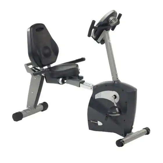
- Page 1 213 Schwinn Recumbent Exercise Bike ® Parts List Full Size Hardware Chart Product Illustration Assembly Instructions...
-
Page 2: Fitness Safeguards And Warnings
FITNESS SAFEGUARDS AND WARNINGS Before starting any exercise program, consult with your physician or health professional. He or she can help establish the correct exercise frequency, intensity (target heart rate zone) and time appropriate for your particular age and condition. The following 3 warnings listed below are also located on the computer console mast of the exercise bike. - Page 3 • A flat area of 5’ x 7’ is suggested to assemble and properly use the 213 exercise bike. • You will need the following tools to complete the assembly:...
-
Page 4: Parts List
Parts List Check Quantity Description Reference # Computer Handlebars Computer Screws Handlebar Post Allen Bolt 8x1.25x16L Wavy Washer Upper HR Wire Upper Computer Wire Lower Computer Wire Lower HR Wire Front Stabilizer Flathead Screw 8x16L Main Frame Pedals Flat Washer Seat Rail Post Rear Stabilizer Seat Rail... -
Page 5: Hardware Chart
P1.25x16mm Stage#6 Allen Bolt M8xP1.25x16mm Screwdriver Screws M8xP1.25x16mm Allen Key Note: Please verify you have all correct parts and quantities before assembling unit. If you are missing items, are short quantities, or have damaged components, please contact Schwinn at 1.800.864.1270. - Page 6 213 Assembly Drawing with Reference Numbers...
-
Page 7: Replacement Parts List
Replacement Parts List Reference # Description Part # Computer 18142 Handlebars 18200 Computer Screws 18094 Handlebar Post 18196 Allen Bolt 8x1.25x16L 18001 Wavy Washer 18098 Upper HR Wire 18086 Upper Computer Wire 18085 Lower Computer Wire 18155 Lower HR Wire 18064 Front Stabilizer 18189... - Page 8 Instructions IMPORTANT!: To ensure ease of assembly please verify the size and quantity of all the required assembly hardware and parts with the enclosed parts list and full size hardware chart. Each step of the assembly process has been broken down into 8 easy-to-follow stages.
- Page 9 Assembly Stage #2 Assemble Seat, Water Bottle Holder, and Seat Backer Assembly hardware required: (8) Screws M4x14L (item #32) (4) M8 Allen Bolts 45 mm long (item #22) (4) Flat Washer Ø8* Ø 16*2T(item #15) Step 2: Attach the right and left WATER BOTTLE HOLDERS (#31) with the SCREWS (#32) to the underside of the SEAT BOTTOM (#33) using the provided screwdriver.
- Page 10 Assembly Stage #3 Assemble Seat Back and Magazine Rack Assembly hardware required: (4) M8 Allen Bolts 16 mm long (item #5) (5) M8 Allen Bolts 35 mm long (item #25) (4) Flat Washer Ø8* Ø 16*2T(item #15) (1) Flat Washer Ø25.4 x 2T (item # 27) Step 4: Attach BACKER SLIDER TUBE (#29) to SEAT FRAME (#23) with 4 ALLEN BOLTS 16mm (#5) and 4 WASHERS (#15).
-
Page 11: Seat Assembly
Assembly Stage #4 Attach Rear Stabilizer and Seat Rail to Seat Assembly Assembly hardware required: (4) M8 Allen Bolts 16mm (item #5) (4) Flat Washers Ø8 * Ø16 * 2T (item#15) (2) Flat Head Screw (item #12) Step 6: Attach the REAR STABILIZER (#17) to the SEAT RAIL POST (#16) with 2 FLAT HEAD SCREWS (#12). - Page 12 Assembly Stage #5 Attach Front Stabilizer Tube and Pedals to Main Unit Assembly Hardware Required: (2) Flat Head Screw (item #12) Step 9: Attach FRONT STABILIZER TUBE (#11) to the MAIN UNIT (#13) with 2 FLAT HEAD SCREWS (#12). Tighten Bolts with provided wrench. Step 10: Attach RIGHT PEDAL (#14) to the right crank arm on the MAIN UNIT (#31).
- Page 13 Assembly Stage #6 Attach Seat Rail to Main Unit Assembly Hardware Required: (3) Allen Bolts 16 mm long (item #5) (3) Flat Washers (item #15) Step 11: Attach the SEAT RAIL HR WIRE (#19) to the LOWER HR WIRE (#10). Carefully slide the seat rail assembly onto the receiver on the MAIN UNIT (#13).
- Page 14 Assembly Stage #7 Attach Handlebar Assembly and Run Cabling Through Handlebar Post Assembly Hardware Required: NONE Step 12: Slide the HANDLEBAR ASSEMBLY (#2) into the receiver on the HANDLEBAR POST (#4). Slide the threaded post into the slider tube and attach the HANDLEBAR ASSEMBLY SLIDER TUBE (#2) and the HANDLEBAR POST (#4) by threading the ADJUSTMENT KNOB (#21) and the SMALL FLAT WASHER (#22) into the threaded post.
- Page 15 Assembly Stage #8 Attach Console Mast to Main Unit Assembly Hardware Required: (4) Allen Bolts 16 mm long (item #5) (4) Curved Washers (item #6) (4) Computer Screws (item #3) Step 14: Before sliding the HANDLEBAR POST (#4) onto the MAIN UNIT (#13), attach both HR CABLES (#7 &...
- Page 16 That’s it! You’re finished and now you can begin to reach your fitness goals! Please reference the Owner’s Manual for information regarding computer operation, product maintenance, warranty information, and general fitness and exercise guidelines. Schwinn Customer Service 1.800.864.1270...
- Page 17 Troubleshooting the Schwinn 213 Recumbent Exercise Bike TIP: Use assembly diagram(s) as reference when troubleshooting unit. PROBLEM: Computer will not start, function, or is blank… (SOLUTION): 1. Ensure the batteries the unit is plugged into a 110v outlet. 2. Check the wiring connections and connector orientation made to the computer.
Need help?
Do you have a question about the 213 and is the answer not in the manual?
Questions and answers