Table of Contents
Advertisement
Quick Links
Advertisement
Table of Contents

Related Manuals for Gefen GEF-DVI-2-HDSDIPRO


Summary of Contents for Gefen GEF-DVI-2-HDSDIPRO
- Page 1 1080P DVI to HDSDI Pro Scaler GEF-DVI-2-HDSDIPRO User Manual www.gefenpro.com...
- Page 2 Notice Gefen LLC reserves the right to make changes in the hard ware, packaging and any accompanying doc u men ta tion without prior written notice. DVI to HDSDI Pro Scaler is a trademark of Gefen LLC © 2011 Gefen LLC, All Rights Reserved...
-
Page 3: Table Of Contents
CONTENTS Introduction Operation Notes Features Connecting and Operating the DVI to HDSDI Pro Scaler Wiring Diagram Panel Layout - Front Panel Panel Descriptions Panel Layout - Back Panel Panel Descriptions IR Remote Layout / Description IR Remote Description IR Remote Installation IR Remote Confi... -
Page 4: Introduction
Complex distribution units allow for professional DVI, 3G-SDI, and HDMI signals to be routed and converted easily and seamlessly, while being backed up by a renowned and dependable technical support team. Gefen invites you to explore the GefenPRO product line and hopes that you fi nd the solution that fi... -
Page 5: Operation Notes
OPERATION NOTES READ THESE NOTES BEFORE INSTALLING OR OPERATING THE DVI TO HDSDI PRO SCALER • On power-up, the DVI to HDSDI Pro Scaler will automatically detect the format of the input signal. • The DVI to HDSDI Pro Scaler contains a master and a slave DVI to HDSDI Scaler unit. -
Page 6: Features
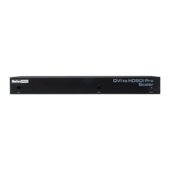
FEATURES Features: • Input and Output Resolutions up to 2048x1080 • 10-bit resolution for greater precision and dynamic range • Proprietary 10-bit motion adaptive video de-interlacing with edge interpolation for HD / SD formats • Frame rate conversion to / from any refresh rate •... - Page 7 PANEL LAYOUT Front Panel...
-
Page 8: Panel Descriptions
PANEL DESCRIPTIONS Front Panel IR Window 1 (Primary Board) Receives signals from the IR Remote Control unit. IR Window 2 (Secondary Board) Receives signals from the IR Remote Control unit. Power Indicator This LED indicator will glow red when the power is turned on. - Page 9 PANEL LAYOUT Back Panel...
-
Page 10: Panel Descriptions
PANEL DESCRIPTIONS Back Panel RS-232 Serial Port Connects to the RS-232 control device. The DVI to HDSDI Pro Scaler may be controlled using this port. See page 26 for more information. 5V DC Locking Power Connector Connects the included 5V DC Locking Power Supply to this receptacle. DVI Input Port (Primary Board) Connect the DVI source device to this port. - Page 11 Wiring Diagram for the DVI to HDSDI Pro Scaler SDI CABLE DVI Source DVI CABLE Clock Generator DVI Source 0 : 0 0 0 : 0 0 : HD-SDI Display Clock Generator Scaler 0 0 : 0 0 : HD-SDI Display GEF-DVI-2-HDSDIPRO...
-
Page 12: Ir Remote Layout / Description
IR REMOTE LAYOUT RMT-8HDS-IR Remote Control Up Cursor Button Moves the selection cursor Up, when using the built-in menu system. Left Cursor Button Moves the selection cursor to the Left, when using the On-Screen Display menu system. Down Cursor Button Moves the selection cursor Down, when using the built-in menu system. - Page 13 IR REMOTE LAYOUT Menu Button Displays the built-in menu system. Right Cursor Button Moves the selection cursor to the Right, when using the On-Screen Display menu system. Enter Button Confi rms the current action. Activity Indicator This LED will be activated momentarily each time a button is pressed.
-
Page 14: Ir Remote Installation
IR REMOTE INSTALLATION Installing the IR Remote Control Battery Remove the battery cover on the back of the IR Remote Control unit. Insert the included battery into the open battery slot. The positive (+) side of the battery should be facing up. Replace the battery cover. -
Page 15: Ir Remote Confi Guration
IR REMOTE CONFIGURATION Resolving IR Code Confl icts In the event that IR commands from other remote controls confl ict with the supplied IR remote control unit, changing the remote channel will alleviate this issue. The IR remote control unit has a bank of DIP switches for setting the remote IR channel. - Page 16 USING THE IR REMOTE CONTROL UNIT Controlling Master and Slave Units The DVI to HDSDI Pro Scaler contains a master and a slave unit. The built-in menu system is controlled using the IR Remote Control Unit. To view the built-in menu system for the master unit, press the Menu button once on the IR Remote Control Unit.
-
Page 17: Menu Functions
MENU FUNCTIONS General > Save Confi guration Saves the current confi guration of the Scaler (Input format, Output format, etc). These settings are restored at power-up. Changes can be made to the current settings and then saved using the Restore Default Confi gurations function (below). -
Page 18: Patterns
MENU FUNCTIONS Patterns > Color Bars Displays the Color Bar pattern using the built-in pattern generator. Patterns > Cross Hatch Displays the Hatch Pattern using the built-in pattern generator. - Page 19 MENU FUNCTIONS Output > Output Format Selects the Output resolution. See page 27 for supported output timings. Output > Link Confi guration Dual Link confi guration: Single Link, Dual Link YCbCr, or Dual Link RGB.
- Page 20 MENU FUNCTIONS Output > Genlock Reference The video signal can be synced (“genlocked”) to an external clock or video input using the Reference In connector. Output > Language Localizes the On-Screen Menu to either English or French.
- Page 21 MENU FUNCTIONS Output > Gamma Correction Allows adjustment of the Gamma coeffi cient, in addition to changing to the sRGB color space or other custom color tables. Input > Video Format Selects the input video format. By default, this option is set to Auto-Detect.
- Page 22 MENU FUNCTIONS Input > Input Graphic Format Selects the input graphic format. This should only be used if using a non- standard timing which the DVI to HDSDI Pro Scaler does not recognize. Input > Clean Aperture Controls the zoom on the input signal. Zooming the image can be controlled using individual axis.
- Page 23 MENU FUNCTIONS Input > Remote Channel Changes the IR channel of the DVI to HDSDI Pro Scaler. The IR channel range is 0 - 3. NOTE: The IR channel can only be changed when using the Master Menu. Picture > Image Colour Adjusts the color levels on the output signal.
- Page 24 MENU FUNCTIONS Picture > Detail Enhancement Adjusts the detail / sharpness of the image. The noise threshold can also be changed. Picture > Noise Reduction Digitally reduces noise in the image.
- Page 25 MENU FUNCTIONS Picture > Motion Threshold Sets the intra-frame motion detection threshold for the de-interlacer. Video artifacts are sometimes introduced when creating a progressive frame from interlaced frames. Use this function to set the motion threshold used by the motion-detection algorithm when de-interlacing. Picture >...
- Page 26 MENU FUNCTIONS Layout > Size and Position Adjusts both the vertical and horizontal size and position of the output signal. Aspect > Full Screen Stretches the output signal to fi t the entire screen.
- Page 27 MENU FUNCTIONS Aspect > Letter / Pillar Box Sets the aspect ratio on the output signal to fi t the letter box or pillar box format. Aspect > Panoramic Panoramic Zoom feature.
- Page 28 MENU FUNCTIONS Aspect > Extract This function extracts a sub-window of the input signal. Use the Extract Size parameter to defi ne the window size based on the percentage of the input. Use the Horizontal and Vertical parameters to select the area of the window to be extract.
- Page 29 IR Remote Control Unit. Refer to the HDSDI RS-232 Serial Communications Manual on the Gefen web site for details on using the RS-232 interface. 5 4 3 2 1...
-
Page 30: Supported Resolutions
SUPPORTED RESOLUTIONS Input Video Formats Supported: 480i 720p/50 1080p/23.98 2K-p/23.98 480p 720p/59.94 1080p/24 2K-p/24 576i 720p/60 1080p/25 576p 1035i/59.94 1080p/29.97 720p/23.98 1035i/60 1080p/30 720p/24 1080i/50 1080p/50 720p/25 1080i/50M 1080p/50M 720p/29.97 1080i/59.94 1080p/59.94 720p/30 1080i/60 1080p/60 Input Graphic Formats Supported: 640x350/85 1024x768/75 1280x1024/85 1080p/60... -
Page 31: Output
SPECIFICATIONS Input Video Bandwidth................165 MHz Output Video Bandwidth..............2 x 1.485 Gbps Maximum Input Resolution..............2048x1080 Maximum Output Resolution......2048x1080 with Dual Link HD-SDI DVI Input Connector..............(2) DVI-I female SDI/HDSDI Output Connector............(4) BNC female Reference Connector..............(2) BNC female RS-232....................DB-9 female Power Supply....................5V DC Power Supply Connector................Locking Power Consumption................20 Watts (max.) Operating Temperature................0 - 40 °C... -
Page 32: Warranty
Gefen warrants the equipment it manufactures to be free from defects in material and workmanship. If equipment fails because of such defects and Gefen is notifi ed within two (2) years from the date of shipment, Gefen will, at its option, repair or replace the equipment, provided that the equipment has not been subjected to mechanical, electrical, or other abuse or modifi... - Page 33 Rev A1 20600 Nordhoff St., Chatsworth CA 91311 1-800-545-6900 818-772-9100 fax: 818-772-9120 www.gefenpro.com support@gefenpro.com This product uses UL listed power supplies.
Need help?
Do you have a question about the GEF-DVI-2-HDSDIPRO and is the answer not in the manual?
Questions and answers