Table of Contents
Advertisement
Quick Links
Advertisement
Table of Contents

Related Manuals for Gefen GTV-HIDEFS


Summary of Contents for Gefen GTV-HIDEFS
- Page 1 ® High-Definition Scaler GTV-HIDEFS User Manual www.gefentv.com...
- Page 2 Notice Gefen, LLC reserves the right to make changes in the hard ware, packaging and any accompanying doc u men ta tion without prior written notice. High-Defi nition Scaler is a trademark of Gefen, LLC © 2011 Gefen, LLC, All Rights Reserved All trademarks are the property of their respective owners.
-
Page 3: Table Of Contents
CONTENTS Introduction Operation Notes Features Panel Descriptions Connecting And Operating The High-Defi nition Scaler RMT-SR-IR Remote Description High-Defi nition Scaler Confi guration 11 RMT-SR-IR Remote Installation 12 IR Code Confi guration 13 Wiring Diagram 14 Specifi cations 15 Warranty... -
Page 4: Introduction
Gefen TV Gefen TV is a unique product line catering to the growing needs for innovative home theater solutions. We specialize in total integration for your home theater, while also focusing on going above and beyond customer expectations to ensure you get the most from your hardware. -
Page 5: Operation Notes
OPERATION NOTES READ THESE NOTES BEFORE INSTALLING OR OPERATING THE HIGH-DEFINITION SCALER • The DVI input on the High-Defi nition scaler will accept an DVI-D (digital) or a DVI-A (analog) video source (connect a VGA and DVI monitor simultaneously using a DVI-I to VGA and DVI-D adapter. Part# ADA-DVI- 2-DVIVGA). -
Page 6: Features
FEATURES Features • Both digital and analog inputs are format converted and pixel re-scaled through the HD Mate Scaler. It outputs a large range of formats and resolutions that will easily match the native resolution/ format of your display to ensure highest picture quality. •... -
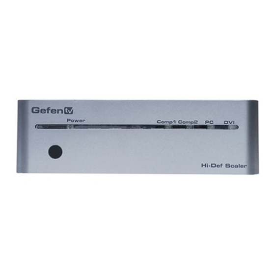
Page 7: Panel Descriptions
PANEL DESCRIPTIONS Front Panel Power Input LED LED Indicator Indicator IR Eye Back Panel Component 1 Toslink Input Component 2Toslink Input Analog Audio Inputs Component Input 2 Component Input 1 Analog Audio DVI-I DVI TOSLINK DVI-I Outputs Output Input Input TOSLINK Output 5V DC Power... -
Page 8: Connecting And Operating The High-Defi Nition Scaler
CONNECTING AND OPERATING THE HIGH-DEFINITION SCALER How to Connect the High-Defi nition Scaler Connect the DVI output on the High-Defi nition Scaler to the display using the supplied DVI cable. Connect either the TOSLINK digital audio output, the stereo mini-jack analog output or the 2 RCA analog audio output to the display or external audio processor using user supplied cables. -
Page 9: Rmt-Sr-Ir Remote Description
RMT-SR-IR REMOTE DESCRIPTION Output - Cycles through the available output resolutions. Please see the section High-Defi nition Scaler CONFIGURATION / Output on page 8 for the output resolution table. Input - Cycles though all of input sources. The selectable inputs are Composite, S-Video, Component, HDMI 1, and HDMI 2. -
Page 10: High-Defi Nition Scaler Confi Guration
HIGH-DEFINITION SCALER CONFIGURATION Entering the Menu System Pressing the Menu button on the included RMT-SR-IR remote control will display the GUI (graphical user interface) for adjustment options. The GUI is overlaid onto the outgoing video to the display. Therefore, the selected source must be outputting a compatible resolution for viewing on the display. - Page 11 HIGH-DEFINITION SCALER CONFIGURATION VIDEO CONTINUED Contrast Adjusts the contrast in increments of 1 on a scale of 1 to 100 (default 50). Brightness Adjusts the brightness in increments of 1 on a scale of to 100 (default 50). Adjusts the hue in increments of 1 on a scale of 1 to 100 (default 50). Saturation Adjusts the saturation in increments of 1 on a scale of 1 to 100 (default 50).
- Page 12 HIGH-DEFINITION SCALER CONFIGURATION VIDEO CONTINUED V-Pos (Vertical Position) Adjusts the image’s vertical position on the screen. Options: • Adjusts in increments of 1 on a scale of 1 to 100 (default is 50) OUTPUT This menu sets the output resolution for all video sources. The OUTPUT button on the RMT-SR-IR remote control cycles through these resolutions when pressed.
- Page 13 HIGH-DEFINITION SCALER CONFIGURATION COLOR Color Tone Sets the color for the appearance of white. Only the USER option will allow customized settings. The USER settings are saved. Options: • Normal - Normal white color appearance (default) • Warm - Slight red shift to white appearance •...
- Page 14 HIGH-DEFINITION SCALER CONFIGURATION OSD (ON SCREEN DISPLAY) H-Pos (Horizontal Position) Adjusts the OSD’s horizontal position on the screen. Options: • Adjusts in increments of 1 on a scale of 1 to 100 (default is 50) V-Pos (Vertical Position) Adjusts the OSD’s vertical position on the screen. Options: •...
-
Page 15: Rmt-Sr-Ir Remote Installation
Note: The RMT-SR-IR ships with two batteries. Only one battery is required for operation, the other battery is complimentary. The optional IR extender allows you to GefenTV IR Remote, relocate your HDMI Switcher and still retain IR Gefen Part # EXT-SR-IR control. Gefen part# EXT-RMT-IREXT... -
Page 16: Ir Code Confi Guration
IR CODE CONFIGURATION How to Resolve IR Code Confl icts In the event that IR commands from other remote controls confl ict with the supplied RMT-SR-IR remote control, changing the remote channel will alleviate this issue. The RMT-SR-IR remote control has DIP SWITCHES for confi guring the remote channel. - Page 17 DISCRETE IR CODES PAGE TITLE Obore duisi tie min eratetuer sustrud tem veniat. Agna facillutat, commodo lestiss endiam iuscidunt num doluptat nulla facil exercidunt utpatie esto el ullaoreet nis ex eraesse ndignisim quametum zzriure feu faccum ad duisi tem quatum doloborem dunt velit lore feugueriurem venibh ercipsustrud ea cor augait ad tin voloborem nos nibh eu feum doloreetum at.
-
Page 18: Wiring Diagram
WIRING DIAGRAM... -
Page 19: Specifi Cations
SPECIFICATIONS Digital Video Amplifi er Bandwidth ............165 MHz Component Video Bandwidth ..............350 MHz Input DDC Signal ................. 5 Volts p-p (TTL) Input Video Signal ................1.2 Volts p-p Single Link Range ..............1080p/1920 x 1200 Input/Output DVI Connector ..........DVI-I (29 pin) female Analog Video Input Connector .......... -
Page 20: Warranty
Gefen warrants the equipment it manufactures to be free from defects in material and workmanship. If equipment fails because of such defects and Gefen is notifi ed within two (2) years from the date of shipment, Gefen will, at its option, repair or replace the equipment, provided that the equipment has not been subjected to mechanical, electrical, or other abuse or modifi... - Page 21 Rev A2 20600 Nordhoff St., Chatsworth CA 91311 1-800-545-6900 818-772-9100 fax: 818-772-9120 www.gefen.com support@gefen.com This product uses UL listed power supplies.
Need help?
Do you have a question about the GTV-HIDEFS and is the answer not in the manual?
Questions and answers