Table of Contents
Troubleshooting

Subscribe to Our Youtube Channel
Related Manuals for Hellenbrand promate 6.0


Summary of Contents for Hellenbrand promate 6.0
- Page 1 Water Management System - Patent Pending Owner’s Manual ©2008-2013 Manufactured by: HELLENBRAND, INC. 404 Moravian Valley Road Waunakee, Wisconsin 53597 Phone: 608-849-3050 • Fax 608-849-7398 Web: www.hellenbrand.com • Email: info@hellenbrand.com...
-
Page 2: Table Of Contents
This owner’s manual is designed to assist owners and installers with the operation, maintenance and installation of your new water softener. It is our sincere hope that this manual is clear, concise and helpful to both owner and installer. We have included detailed in- structions on general operating conditions, pre-installation and installation instructions, start-up, and timer and meter programming. -
Page 3: Job Specification Sheet
JOb speCifiCaTiOn sheeT MODEL NO. __________________________________________________________________________________________ *WATER TEST AT TIME OF INSTALLATION _______ Hardness CaCo (gpg) ______ Other______________________ _______ Iron (ppm) ______ Other______________________ _______ pH ______ Other______________________ OPTIONAL RELAY SETTINGS ALT MAV AUX MAV ______ Alternator system enabled ______ Brine Reclaim Enabled _______ Off ______ Reclamation mode enabled ______ Separate Source Enabled... -
Page 4: Soft Water Basics
sOfT WaTer basiCs hardness Excess amounts of calcium and magnesium in water produce hardness. A water softener removes the majority of calcium and magnesium to produce softened water. Hardness is measured in terms of grains. (This grain weight is derived from the average weight of a dry grain of wheat.) When your water is tested the grain hardness is calculated and expressed as grains per gallon (gpg). -
Page 5: Pre-Installation Check List
pre-insTallaTiOn CheCk lisT (All electrical & plumbing should be done in accordance to all local codes) Water Pressure: A minimum of 25 pounds of water pressure with lime and/or iron must be replaced. If piping is blocked with iron, additional equipment must be installed ahead of the water (psi) is required for regeneration. -
Page 6: Installation Instructions
insTallaTiOn insTruCTiOns (All electrical & plumbing should be done in accordance to all local codes) CAUTION: • Do not use vaseline, oils or other hydrocarbon lubricants or 5. The drain connection may be made using either 5/8” polytube (See figure 6a, page 6) or a 3/4” female adapter. If solder- spray silicone anywhere. -
Page 7: Programming
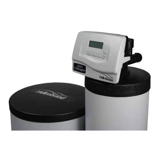
prOGraMMinG General information 12:00 The ProMate-6.0 control valve is the “brain” of your water soft- ener. It consists of the valve body and powerhead with solid state microprocessor. The display panel (see Figure 7) consists of the LCD display and five push buttons which are used in displaying and program- ming the water softener settings. -
Page 8: Installer Programming
seT TiMe Of DaY = Up Arrow = Down Arrow Step 1 Step 1 - Press SET CLOCK. Step 2 - Current Time (hour): Set the hour of the day using or buttons. AM/PM toggles after 12. Press NEXT to go to step 3. 6:35 SET TIME Step 2... -
Page 9: Softener Setup
Manual regeneration "REGEN TODAY" CAPACITY REMAINING Sometimes there is a need to regenerate the system sooner than when the system calls for it, usually referred to as manual regeneration. There may be a period of heavy water usage because of guests or a heavy laundry day. To initiate a manual regeneration at the preset delayed regeneration time, press and release “REGEN”. - Page 10 STEP 4 S – Select the time for the second cycle (which in this example is SOFTENING) SOFTENING TIME Step 4S using or button. Press NEXT to go to Step 5S. Press REGEN to return to the previous 120:00 step.
- Page 11 STEP 12 S – Set Regeneration Time Options using the or button. If value is set to: DELAY + IMMEDIATE Step 12S • “DELAY” means regeneration will occur at the preset time; (page 8, step 4) REGEN • “IMMEDIATE” means regeneration will occur immediately when the gallons capacity reaches 0 (zero);...
- Page 12 STEP 20S – Use up and down arrows to select number of gallons per relay RELAY 1 SET POINT Step 20S activation of regen gallon setting. Range: 0.1 -20,000 gallons. Press NEXT to go to Step 21S. STEP 21S – If Off or Time was selected in previous steps, this screen does not RELAY 1 DURATION Step 21S...
-
Page 13: Service Reminder
serviCe reMinDer STEP 27S – Set scheduled service display using or buttons. Available options are OFF, TIME, SERVICE ALARM Step 27S BOTH ON GAL or BOTH. Selecting OFF disables this feature. If OFF is selected, press NEXT to exit System Setup. -
Page 14: Valve History
STEP 5D – Volume of water used, 63-day usage history: This display shows day 0 (for today) STEP 5D USAGE HISTORY and 1 (for yesterday) will show day 2 (which would be the day before yesterday) and flashes the volume of water treated on that day. Continue to press the button to show the volume of water treated for the last 63 days. -
Page 15: Cycle Sequence
CYCle seQuenCe Anytime cycle sequence is modified, softener set-up will revert to Cycle Options manufacturer setting and must be reprogrammed as desired. REGENERANT BACKWASH FILL DRAW-DN Cycle Sequence instructions allows the operator to set the order of the RINSE cycle. The Softener System Setup allows the operator to set how long SOFTENING the cycles will last. - Page 16 Confi guring the Control Valve to operate with Clack System Controller: Select System Board Enabled to link the Control Valve to the Clack System Controller. For STEP 9CS – Configuring the Control Valve to operate with the Hellenbrand System Con- SYSTEM BOARD...
- Page 17 STEP 5CS Step 5CS – Set Auxiliary Drive Output (MAV only) to operate in one of three modes: • Set RECLAIM (Time): Allows Auxiliary MAV to switch positions at a set time in relation to the start of regeneration for a preset duration, independently of the actual regeneration status. Up to 3 bypass events are possible.
- Page 18 Brine Reclaim: When Reclaim is selected as trigger for Auxiliary MAV Drive, a portion of the brine can be diverted after it has passed through the resin bed. Brine discharge contains unused salt that can be used for brine make-up for the next regeneration. A motorized alternator valve (MAV) must be connected to the two-pin connector labeled AUX DRIVE located on the circuit board or error code 106 will result.
- Page 19 STEP 15CS – Press the or buttons until selection of first cycle appears in left upper corner, in BACKWASH Step 15CS CYCLE 1 this example BACKWASH is selected. Press NEXT to go to Step 16CS. Press REGEN to return to previous step.
-
Page 20: Water Softener Disinfection
WaTer sOfTener DisinfeCTiOn The construction materials of your water softener will not support such trade names such as Clorox, Linco, Bo Peep, White Sail bacterial growth nor will these materials contaminate a water supply. and Eagle Brand Bleach. If stronger solutions are used, such However, the normal conditions existing during shipping, storage, as those sold for commercial laundries, adjust the dosage and installation indicate the advisability of disinfecting a softener after... -
Page 21: Troubleshooting
TrOuble shOOTinG PROBLEM CAUSE CORRECTION After resolving the cause of any error code or any service work on valve, press NEXT & REGEN simultaneously for 5 seconds or disconnect power supply for 5 seconds at PC board and reconnect to resynchronize software with piston position. valve errOr CODes Error Code 101 - Unable to recognize A1. -
Page 22: Trouble Shooting
TrOuble shOOTinG PROBLEM CAUSE CORRECTION 2. Control valve does not regenerate A. Transformer unplugged A. Connect transformer automatically when REGEN button B. No electric power at outlet B. Repair outlet or use working outlet is depressed and held C. Broken drive gear or drive cap assembly C. - Page 23 TrOuble shOOTinG PROBLEM CAUSE CORRECTION 13. Iron in softened water. A. Iron has fouled resin bed. A. Use iron reducing resin cleaner to clean resin bed, and increase salt dosage or regenerate more frequently or rebed softener. Install an Iron Curtain System ahead of the softener.
-
Page 24: Parts Diagrams
prOMaTe-6.0 COnDiTiOner & brine Tank asseMblies Item Description Part # Metered Control Valve 104306 PM6-32 (see page 26 for detailed components) Specify Model - ie 24, 32, 48 Top Diffuser 101539 3&4 Mineral Tank Assembly Item 3 only Item 4 only Not Shown Mineral Tank Distributor Assy... - Page 25 frOnT COver anD Drive asseMblY ITEM NO. DESCRIPTION QTY. ORDER NO. 103473 PM 6.0 Cover Assy w/Label 102096 Motor 101262 Drive Bracket & Spring Clip 109807 PM 6.0 - PC Board 101746 Drive Gear 12x36 101459 Drive Gear Cover See Page 24 for Relay Wiring Relay Kit Options: 103724 PCM Relay Installed...
- Page 26 inJeCTOr Cap, inJeCTOr sCreen, inJeCTOr, pluG anD O-rinG ITEM NO. DESCRIPTION QTY. ORDER NO. 101375 Injector Cap 102159 O-ring 135 102457 Injector Screen 102319 Injector Assy. z Plug-Filter 101825 Injector Assy. A Black 101826 Injector Assy. B Brown 101827 Injector Assy. C Violet 101828 Injector Assy.
- Page 27 Drain line - 3/4” QTY. ITEM NO. DESCRIPTION ORDER NO. 101414 Elbow Locking Clip 101871 Polytube Insert, 5/8” Optional 102131 Nut 3/4” Drain Elbow Optional 101618 Drain Elb 3/4" Male Assy-Vent Optional 101619 Drain Elb 3/4” Male Assy-No Vent 102153 O-ring 019 102406 DLFC Retainer Assy.
- Page 28 WaTer MeTer anD MeTer pluG QTY. ITEM NO. DESCRIPTION ORDER NO. 102141 Nut 1” QC 102051 Meter Assy. 102687 Turbine Assy. 102165 O-ring 215 102321 Meter Plug Assy.** *Order number 102051 includes 102687 and 1102165, which are item numbers 3 & 4. **Only used if metering is not to be done (time clock units) Page 20 WS1 &...
-
Page 29: Installation Fitting Assemblies
insTallaTiOn fiTTinG asseMblies QTY. QTY. ITEM NO. DESCRIPTION ITEM NO. DESCRIPTION ORDER NO. ORDER NO. 102141 Nut 1” Quick Connect 102141 Nut 1” Quick Connect 102437 Split Ring 102437 Split Ring 102165 O-Ring 215 102165 O-Ring 215 106761 Fitting 1” PVC Male NPT Elbow. 106762 Fitting 3/4”... - Page 30 QTY. QTY. ITEM NO. DESCRIPTION ITEM NO. DESCRIPTION ORDER NO. ORDER NO. 102141 Nut 1” Quick Connect 102141 Nut 1” Quick Connect 102437 Split Ring 102437 Split Ring 102165 O-Ring 215 102165 O-Ring 215 106787 Fitting 1-1/4"&1-1/2" Brass Sweat 106786 Fitting 1-1/4"&1-1/2"...
-
Page 31: Specifications
6.0 sYsTeM speCifiCaTiOns MODEL PM6-024 PM6-032 PM6-032-10 PM6-048 PM6-064 PM6-096 PM6-128 PM6-160 PM6-192 PM6-032DMT FACTORY PRESET MINUTES Backwash; Min Brine; Min. Fast Rinse; Min Refill-Minutes -Low Salting* 12.0 16.0 20.0 24.0 -Medium Salting 10.0 13.5 20.0 27.0 33.5 40.0 -High Salting 10.0... -
Page 32: Injector Flow Graphs
inJeCTOr flOW Graphs YELLOW, ORDER NO. 101831 GREEN, ORDER NO. 101832 ORANGE, ORDER NO. 101833 LIGHT BLUE, ORDER NO. 101834 WHITE, ORDER NO. 101829 LIGHT GREEN, ORDER NO. 101835... -
Page 33: Programing Options And General Specifications
prOGraMMinG OpTiOns Reserve Regeneration Days Results Gallons Override Type (Reserve capacity estimate based on history of water usage) Reserve capacity automatically estimated. Regeneration occurs when gallons capacity falls below the reserve capacity at the next AUTO DELAYED REGEN Regen Set Time. Reserve capacity automatically estimated. -
Page 34: Warranty
If a part described above becomes defective within the specified warranty period, you should notify your ProMate 6.0® sales representative and arrange a time during normal business hours for the inspection of the water conditioner at the original installation site. Any part found defective within the terms of this warranty will, at Hellenbrand, Inc.’s option, be repaired or replaced.
Need help?
Do you have a question about the promate 6.0 and is the answer not in the manual?
Questions and answers