Advertisement
Advertisement
Table of Contents

Subscribe to Our Youtube Channel
Related Manuals for Telex Audiocom SPS-2000


Summary of Contents for Telex Audiocom SPS-2000
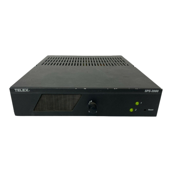
- Page 3 3. ßeset The power status indicators will remain red after sensing a problem, until power is removed from the SPS-2000 or reset is pressed. Press ßesetafter the problem has been resolved or the appropriate channel connector has been disconnected.
- Page 4 5. SPEAKER Input Jacks These jacks can be connected to the SPEAKER outputs of a US-2000 or ES-4000 station. They may also be used to connect audio input from some other line-level program source (an auxiliary output from a radio or tape player for example).
- Page 5 Figure 2. Interna1 Switches and Jumpers...
- Page 6 CONNECTOR PIN CONFIGURATIONS Speaker Inputs Type: RCA Phone Jack Tip: Speaker output high Sleeve: Common lntercom Channel Connectors Type: XLR-3M Audiocom Mode (Internal switch S200 set to BAL position) Pin 1 Common Pin 2 +24 VDC output and audio termination Pin 3 +24 VDC output and audio termination Clear-Com Mode (Internal switch S200 set to UNBAL position)
- Page 7 SPECIFICATIONS GENERAL Output Voltage: 24 f 1 VDC Output Current: 2A at 21 1 VDC Output Impedance: 150R f5%, unbalanced 300R f 1 0%, balanced Input Power Requirements: 92 to 255 VAC, 50 to 400 Hz Environmental Requirements: 0°C to 50°C; 0% to 95% humidity, non-condensing Dimensions: 1.75"...
- Page 8 Non-Warranty Repairs Equipment that is not under warranty must be sent prepaid to Telex. If requested, an estimate of repair costs will be is- sued prior to service. Once your approval for repair, and repair of equip- ment is completed, the equipment will be returned on a collect basis.
Need help?
Do you have a question about the Audiocom SPS-2000 and is the answer not in the manual?
Questions and answers