Table of Contents

Related Manuals for Telex Audiocom US-2000


Summary of Contents for Telex Audiocom US-2000
- Page 1 ® T elex Operating Instructions US-2000 User Station ® Audiocom System t e n L i s i l l A l l S id l u m Intercom ® - 2 0 t e n L i s...
-
Page 2: Fcc Statement
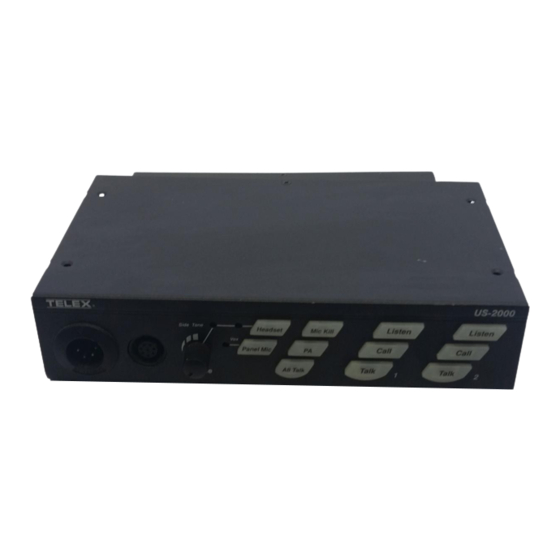
18 channels. ES-4000 Expansion Stations can be “daisy chained” to the US-2000 to add four channels at a time to the intercom system. Each channel can be programmed for talk, listen or both. - Page 3 Figure 1. Front and Rear Panel Controls...
-
Page 4: External Connections & Controls
Clear-Com Setup in this manual. The US-2000 is factory set to allow all channels (including those of any attached ES-4000 units) to be heard through a single powered speaker, such as the Audiocom® SPK-1000. If the user wants to have each channel go to a separate powered speaker, three jumpers must be changed as described in the section on Speaker Setup in this manual. - Page 5 3. VOLUME Control Use this control to adjust the headset listen level. 4. SIDETONE Control When using a headset, this control adjusts your own voice level heard in the earphones. To adjust the level, tap the Headset key once to turn on the headset microphone. Then, use a small flat-blade screwdriver to increase or decrease your voice level while talking into the microphone.
- Page 6 The PA function allows the user to talk over a public address system that is connected to the rear of the US-2000. With either the Head- set or Panel Mic selected, press and hold the PA key to talk on a public address system connected to the P.A.
- Page 7 Call keys are lit, Headset Audible Call Alert is enabled). Press either Call key to enable or disable Headset Audible Call Alert on both US-2000 channels. Tap the Mic Kill key to exit the feature setup. 10. Talk keys There is a Talk key for each channel.
- Page 8 1 level heard on intercom channel 1. The VOL PGM 2 control adjusts the program 2 level heard on intercom chan- nel 2. As supplied, the US-2000 does not interrupt the program in- puts during talk. Program interrupt during talk requires an internal switch change (see Table 1, switches SW2-4 and SW2-5).
-
Page 9: Internal Switches, Jumpers And Adjustments
16. EXP OUT Jack Connects audio and data to the EXP IN jack of an optional Telex® ES-4000 expansion station. 17. SPEAKERS Output Jacks Connects channel audio to the Input jacks of an optional Telex® SPK-1000 Powered Speaker. May also be connected to the auxil- iary input of an amplifier. - Page 10 Figure 2. The adjustments are also accessible from the underside of the US-2000, as shown in Figure 3. Figure 2. Internal Switches, Jumpers and Adjustments NOTE: To activate a changed switch or jumper setting, either perform a RESET or cycle the power on and off.
- Page 11 CANCELLATION CHN 2 RETURN CANCELLATION Figure 3. Adjustments Accessible From the Underside Clear-Com Setup Make the following switch and jumper changes when the US-2000 is used with Clear-Com equipment: · SW1 (BAL/UNBAL) must be placed in the UNBAL position. ·...
- Page 12 DIP Switches (SW2) Table 1. SW2 Functions and Settings SWITCH NUMBER SWITCH FUNCTION Headset audible key press beep on/off On: No beep Off: Beep activated Mic Kill on/off (Enables/disables another user station from killing the microphone on this station) On: Mic kill enabled Off: Mic kill disabled Channel 1 20-kHz call/send On: Enable 20 kHz signalling...
- Page 13 Balanced/Unbalanced Switch (SW1) Set this switch to the balanced (BAL) position to use the US-2000 with Audiocom® intercom channels. Set the switch to the unbalanced (UNBAL) position for use with a Clear-Com® intercom system. (The factory default setting is the balanced position for use with Audiocom®.) Table 2.
-
Page 14: Connector Pin Configurations
Adjustments The following adjustments are accessible either internally (refer to Figure 2) or from the underside of the US-2000, as shown in Figure 3. Return Cancellation Adjustments (R187, R188) Adjusted at the factory to cancel audio output that may be re- flected from the line. - Page 15 Program Inputs Type: DB9F Pin 1 Ground Pin 2 Program 1 input low Pin 3 Program 2 input low Pin 4 Pin 5 Pin 6 Program 1 input high Pin 7 Program 2 input high Pin 8 Pin 9 P.A. Output Type: 1/8-inch Stereo Phone Jack Unbalanced Wiring (-000 Model) Tip: PA output high...
- Page 16 Intercom Channel Connectors Type: One XLR-3M and XLR-3F pair for each channel Audiocom® Mode (Internal switch SW1 set to BAL position) Pin 1 Common Pin 2 Intercom audio low and +24 VDC input Pin 3 Intercom audio high and +24 VDC input Clear-Com Mode (Internal switch SW1 set to UNBAL position) Pin 1 Common...
-
Page 17: Specifications
SPECIFICATIONS GENERAL Power Requirements: Channel supplied: 24 VDC nominal (12 to 30 VDC), 65 to 150 mA External supply: 12 to 15 VDC, 65 to 150 mA Environmental Requirements: Storage: -20ºC to 80ºC; 0% to 95% humidity, non-condensing Operating: -15ºC to 60ºC; 0% to 95% humidity, non-condensing Dimensions: 1.75"... -
Page 18: Program Input
Unbalanced Intercom Channel: Output Level: 200 mVrms ±10% Input Impedance: 150W Bridging Impedance: greater than 10,000W Return Cancellation: -40 dB, 35 dB adjustable range Call Signalling: Send: 11 ±3 VDC Receive: 4 VDC minimum PROGRAM INPUT Voltage Gain Range: 25 ±3 dB Output Level: 1.0 Vrms nominal, 2.3 Vrms maximum Input Impedance:... - Page 19 Total Harmonic Distortion: Less than 0.2% at 200 mW Sidetone: 18 ±2 dB, adjustable PANEL MICROPHONE AMPLIFIER: Voltage Gain: · Mic to CHN; 25±3 dB, before limiting · Mic to Headphone; adjustable, 45 dB ±10% maximum, into 150W · Mic to PA; 15 ±3 dB, 235 mVrms ±10% Frequency Response: 200 Hz to 8 kHz +1/-3dB Total Harmonic Distortion:...
-
Page 20: Factory Service
Non-Warranty Repairs - Equipment that is not under warranty must be sent prepaid to Telex. If requested, an estimate of repair costs will be issued prior to service. Once your approval for repair, and repair of equipment is completed, the equipment will be returned on a collect basis. - Page 21 US-2000/ES-4000 QUICK REFERENCE Reset US-2000 Press All Talk and Listen 1 Reset ES-4000 Press All Talk 4 and Listen 5 Test signal on Press All Talk and PA , then tap Call Test signal off Tap Call , then tap any other key...
- Page 22 TELEX COMMUNICATIONS, INC. • 12000 Portland Ave. S., • Burnsville, MN 55337 U.S.A. 9300-7322-000 Rev. D September 1996...
Need help?
Do you have a question about the Audiocom US-2000 and is the answer not in the manual?
Questions and answers