
Related Manuals for Telex RTS SPK300L


Summary of Contents for Telex RTS SPK300L
- Page 1 MODEL SPK300L TW INTERCOM SYSTEM PORTABLE SPEAKER USER STATION 9300-3505-00 Rev F 08/2005...
- Page 2 OTICE The product information and design disclosed herein were originated by and are the property of Telex Communications, Inc. Telex reserves all patent, proprietary design, manufacturing, reproduction, use and sales rights thereto, and to any article disclosed therein, except to the extent rights are expressly granted to others.
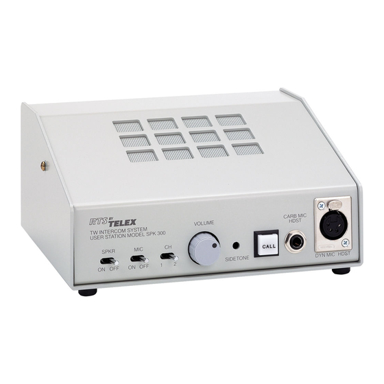
- Page 3 DESCRIPTION The Model SPK300L, a Portable Speaker User Station, is a component used in the TW INTERCOM SYSTEM. Each User Station is a communications unit along a multi-unit conference bus. Figure 1, “TW System Concept Block Diagram,” on page ii, shows User Station interconnection, and User Station connection to the system power supply.
-
Page 4: Operational Controls
200 ohm resistor and a 10 microfarad capacitor in series. (See the Application Diagrams in the TW Intercom Systems Technical Manual). A TW System Power Supply terminates a line with 200 ohms. Operational Controls The SPK300L User Station has the following controls, described and shown in Section 3: • Channel Select Switch •... -
Page 5: Specifications
Specifications SPK300L Block Diagram FIGURE 1. Specifications Audio Line 1 volt, peak (0 dBm voltage-equivalent) Voltage Average -20 dBV to -10 dBV Speech Level Range Absolute 3 volts, peak (linear limit) Maximum Speech Level Audio Line 200 50 ohms, 75 Hz to 20 kHz... - Page 6 Introduction Limiter Range 50 dB Carbon Mic 10 milliamps, nominal Excitation Current CURRENT SOURCE Transfer Ratio 5 milliamps/1.5 volts Output 5 milliamps into 200 ohms HEADPHONE AMPLIFIER Overall 24 dB Voltage Gain Overall 9 volts peak-to-peak into 25 ohms Voltage Gain Output Power Headset Station: 1/2 watt into 25 ohms Speaker Station: 2 watts into 8 ohms...
-
Page 7: Mechanical Installation
MECHANICAL INSTALLATION The Model SPK300L Portable Speaker User Station is 4.0 inches (101.6 mm) high X 8.0 inches (203.2 mm) wide X 8.0 inches (203.2 mm) deep. Additional depth should be allowed for the rear panel XLR-type line connectors. When installing this unit, allow space for control access, cabling and servicing. - Page 8 (over 1/2 mile (804 m)). Typical operating distance for one SPK300L station is 1/2 mile (.80 km), and for one SPK300L, 1/3 mile (0.53 km) using a normal # 22 AWG conductor size.
- Page 9 USER STATION CONNECTIONS Routing the TW Intercom System cables along the same ductways and pathways as power cabling can increase the noise and hum levels. Moisture / Contamination Protection When using equipment in the rain, always protect the equip- ment with plastic covers----also, make sure all cable con- nectors are lifted out of the mud or snow and protected with plastic bags.
- Page 10 INSTALLATION...
-
Page 11: Operation
Operating Controls The table below lists the Model SPK300L operating controls. The reference numbers in the table correspond to the circled numbers in Figure 3-1. Model SPK300L Operating Controls TABLE 1. REF NO. NAME Channel Select Switch Mic ON/OFF Toggle... - Page 12 RTS Systems, uses a power supply assembly (RTS # 9020-4425-00), which is 117 VAC, 60 Hz in , 24 VDC 400 mA out. To modify the RMS300 or SPK300L for local power operation, do the following: Remove diode D26 from the CC300 P.C. board.
- Page 13 Wire PG, 4-pin plug (Calrad #30-453, RTS # 2013-0016-00) to the external supply: Pin 1 = common, Pin 2 = external supply +. Plug P6 into J6 on the RMS300 or SPK300L back panel. NOTE: If using RTS local power option kit 9002-5541-00, the external supply will already be wired to P6.
- Page 14 OPERATION...
- Page 15 CHAPTER 4 DRAWINGS...
- Page 16 Schematic Diagram, CC300, page 2 of 3 Schematic Diagram, CC300, page 3 of 3 Wiring for External Microphones Servicing Diagram, Model RMS300/SPK300L, Wiring Diagram, pg. 1 of 7 SPK/RMS300 Standard -L Option and Local Power Option Wiring Diagram, pg. 2 of 7 SPK/RMS300 3CH and 3CH-L Options Wiring Diagram, pg.
- Page 37 NOTES...
- Page 38 12000 Portland Avenue South • Burnsville, MN 55337 • U.S. A.
Need help?
Do you have a question about the RTS SPK300L and is the answer not in the manual?
Questions and answers