
Related Manuals for Telex SS1000


Summary of Contents for Telex SS1000
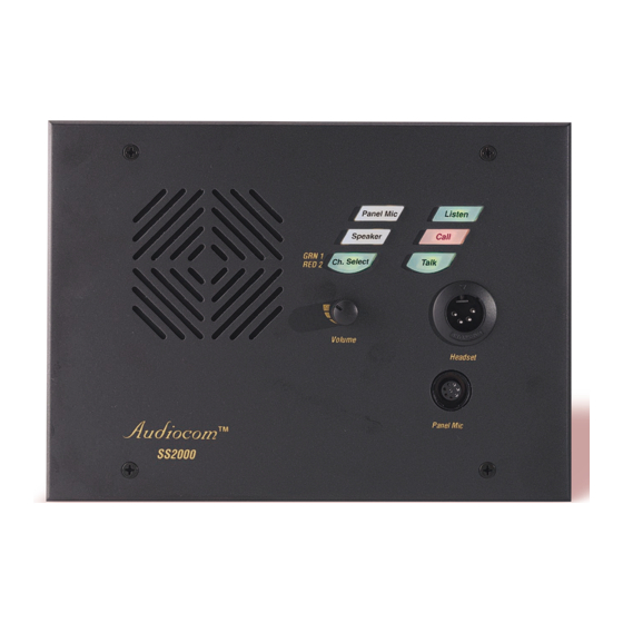
- Page 1 ® T elex User Instructions SS2000 “S” Box SS2000 “P” Box SS2000 “U” Box Model SS1000 / SS2000 Intercom Speaker Stations ® Audiocom Intercom Systems ®...
- Page 2 This product meets Electromagnetic Compatibility Directive 89/336/EEC. Introduction. Thank you for purchasing the Audiocom SS1000 / SS2000 Intercom Speaker Station. We hope the many design features of this product will satisfy your inter- communication requirements for many years to come. To get the most out of your new intercom station, please take a few moments to look through this book- let before using the Intercom Speaker Station for the first time.
-
Page 3: Table Of Contents
Table of Contents Description Features . Installation Unpacking Configuration Pre-check . Intercom Channel Connections . Headset / Headphone / Microphone Connections . Power-Up Sidetone Adjustment Operation Channel Select (SS2000 Only) . Headset / Headphone / Speaker / Microphone Selection Receiving Calls Calling an Intercom Channel Specifications Factory Service and Parts Information... -
Page 4: Description
SS2000 provides switch-selectable access to either of two intercom channels. Both the SS1000 and SS2000 come in three versions to suit a variety of applications. The “S” box is a portable version. It has a carrying handle and dual “loop-through” inter- com connectors which permit stations to be quickly interconnected using prefabri- cated cables. -
Page 5: Features
Intercom Talk Key: Both momentary (push-to-talk) and latching (hands-free talk) are pos- sible. The SS1000 / SS2000 also features a "mic kill receive" circuit, which allows an op- erator at a remote master station (such as the US2000A) to turn off the SS1000 / SS2000 talk key. - Page 6 Aud iocom ® 13. Balanced / Unbalanced Selector Switch: This switch sets the intercom station for compati- bility with either Audiocom or Clear-Com* intercom systems. 14. Mounting Holes (Figure 3): The “U” box is typically mounted in a wall. The “S” and “P” boxes may be mounted on a wall, desktop, or console.
- Page 7 9.125“ 231.78 mm 9.625 244.48 mm 6.102 155.0 mm 8.11" 206 mm 3.937" 100 mm 6.102" 155 mm 2.7" .812" Dia (3 Places) 69 mm 1.575" 40 mm Figure 3. Dimensions 2.125“ 53.98 mm 6.75" 171.5 mm "S" Box 4.125" "...
-
Page 8: Installation
Installation Unpacking Each SS1000 / SS2000 is supplied with the following items. Contact the shipper or your Audiocom dealer immediately if anything is damaged or missing. Detach and fill out the registration card and return it to Telex to properly register your intercom station. - Page 9 Table 1. DIP Switch Settings Switch Description Number Not used Call signal method Incoming call beep Microphone type Speaker beep for incoming call Not used Not used Not used Incoming Call Beep (DIP Switch 3) Incoming calls are always indicated by a red-flashing call key. If you also want in- coming call beep in headphones, set DIP switch 3 to the Open position (default).
- Page 10 This switch is set at the factory to the Balanced, or BAL, position for use with Audiocom intercom channels. Set the switch to the Unbalanced, or UNBAL, position for use with a Clear-Com intercom system. Sidetone Trimmers (Figure 2, item 12) These are normally adjusted after all connections are completed.
-
Page 11: Intercom Channel Connections
“S” and “P” box versions, since these versions are usually connected with relatively short cables of less than 200 ft. Figure 4, page 13, illus- trates a phantom powered intercom system with "S" and "P" type stations. Figure 6, page 15, illustrates phantom power for "U" boxes. - Page 12 "U" boxes. As long as a system power supply (PS2000L, SPS2000A, etc.) is lo- cated somewhere in the intercom system, the proper terminating impedance will still be supplied for all stations. However, if all stations are locally powered, and there is no system power supply, a special line termination must be installed as described below.
- Page 13 SS2000 "S" Box Figure 4. A two-channel Audiocom intercom system powered by a PS2000L Power Supply. The power supply is set to isolate mode. In this mode, each channel is a separate party line, and current per channel is limited to 1 amp. Note that both single- and two-channel intercom stations may be connected by using “Y”...
- Page 14 Aud iocom ® TYPICAL 1-CHANNEL CABLE WIRING Pair 1 Pair 2 Shield Cable Type: 22AWG Stranded, 2-Pair Twisted-wire, with Shield Connector Type: 3-Pin XLR Audio (Neutrik or Switchcraft) Pin 1: Common Pin 2: Channel Audio / Power Pin 3: Channel Audio / Power Shield : Earth ground TYPICAL 2-CHANNEL CABLE WIRING...
- Page 15 1 amp. Note that both SS1000 and SS2000 stations may be connected, depending on each locations’ need to communicate with one or two channels. SS1000 stations may be connected to either channel one or two.
- Page 16 LOCAL POWER 12 to 15 VDC, 250 mA Figure 7. An example of an Audiocom intercom system using all locally powered “U” box stations, with no power being distributed on the intercom channels (dry lines). Since an Audiocom power supply is not used, the installer must connect a line termination somewhere in each channel for proper operation.
- Page 17 Denotes shield. *Shield: Earth ground (Connect at power supply only. Do not short to DC common) Figure 8. Audiocom mode connections for a SS1000 Intercom Station in a “U” box. Note: For Clear-Com connection, use the Unbalanced Mode Intercom Channel pin-out information listed on page 25.
- Page 18 Au d io c o m ® TO ADDITIONAL SINGLE- OR TWO-CHANNEL STATIONS Shield* PIN 1 Cable Type: 22AWG Stranded, 3-Pair Twisted-wire, with Shield Denotes twisted pair. Denotes shield. *Shield: Earth ground (Connect at power supply only. Do not short to DC common) Figure 9.
-
Page 19: Headset / Headphone / Microphone Connections
DIP switch 4 is properly set for either balanced or unbal- anced microphone. See "Dynamic Microphone Type Selection", page 9. To connect a Telex model EGM-12N or EGM-18N panel microphone, line up the arrow on the top of the microphone with the top of the connector on the in-... -
Page 20: Power-Up
Sidetone Adjustment The SS1000 and SS2000 use full-duplex audio (the same as conventional telephone lines) in which the talk and listen audio are sent and received on the same wires. Thus, when you talk, you also here your own voice back as with a telephone. - Page 21 5. SS2000 only: activate channel 2 and repeat the above steps to adjust the channel 2 sidetone. 6. Install the intercom station mounting screws after completing the adjustments. The station is now ready for use. If you are using headphones that completely enclose the ears, adjust sidetone as follows: 1.
-
Page 22: Operation
Aud iocom ® Operation Channel Select (SS2000 Only) Tap the Ch Select key to select channel 1 or 2. The key is green when channel 1 is se- lected and red when channel two is selected. Headset / Headphone / Speaker / Microphone Selection To use a headset or telephone style handset, set the Speaker and Panel Mic keys to off. - Page 23 2. Press and hold the Call key. An inaudible call signal will be sent, and the Listen key will automatically turn on. 3. When you hear a response, release the Call key and activate the talk key. 4. Turn off your Talk and Listen keys to end the conversation.
-
Page 24: Specifications
Aud iocom ® Specifications General Power Requirements: Phantom Power: 24 VDC nominal (12 to 30 VDC), 175 mA Local Power: 12 to 15 VDC, 250 mA Dimensions: See Figure Environmental Requirements: Storage: -20°C to 80°C; 0% to 95% humidity, non-condensing Operating: -15°C to 60°C;... - Page 25 Intercom Channel, Unbalanced Mode (SW1 set to Unbalanced or UNBAL position) Output Level: 1 Vrms ±10% Input Impedance: 150 ohms Bridging Impedance: greater than 10,000 ohms Call Signaling: Send: 11 ±3 VDC Receive: 4 VDC minimum Connector Type: Six-position terminal block with screw-in wire clamps Pin 1 Common Pin 2...
-
Page 26: Factory Service And Parts Information
Non-Warranty Repairs - Equipment that is not under warranty must be sent prepaid to Telex. If requested, an estimate of repair costs will be issued prior to service. After your approval and completion of the repairs, the equipment will be returned on a col- lect basis. - Page 27 Addendum Document Affected: SS1000/SS2000 User Instructions, Publication Number 9350-7620-000 Rev. D Addendum Number: 1 General Instructions: Use this addendum with Revision D of the user instruc- tions. This information will be included in Revision E. When setting the DIP switches, it is difficult to identify the open and closed po- sitions.
- Page 28 ® TELEX COMMUNICATIONS, INC. 12000 Portland Ave. So., Burnsville, MN 55337 U.S.A. 9350-7620-000 Rev. F, 1/01...
Need help?
Do you have a question about the SS1000 and is the answer not in the manual?
Questions and answers