Table of Contents
Advertisement
Quick Links
Download this manual
See also:
Instructions for Using
Advertisement
Table of Contents

Related Manuals for Telex Audiocom EMS-4001


Summary of Contents for Telex Audiocom EMS-4001
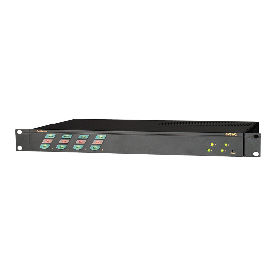
- Page 1 User Instructions Model EMS-4001 Expansion Master Station ® Audiocom Intercom Systems 9350-7713-000 Rev. B, 3/2005...
- Page 2 If a return through the dealer is not possible, obtain a The sole obligation of Telex during the warranty period is to RETURN AUTHORIZATION from: provide, without charge, parts and labor necessary to remedy...
-
Page 3: Table Of Contents
Table of Contents Description ................4 Features ..................4 Installation ................. 5 Unpacking ............................. 5 Configuration Pre-check ............6 Balanced/Unbalanced Switch ...................... 6 Direct Program Listen Enable/Disable Jumpers ............... 6 Sidetone Trimmers ........................6 Mounting Configurations ......................8 Connection Notes .......................... 8 Cables ............................. -
Page 4: Description
Up to four EMS-4001 Expansion Master Stations may be connected to the MS- 2001 to add up to 16 channels (18 channels total). The MS-2001 microphone is used to talkback to the EMS-4001 channels, and the MS-2001 speaker is typically used for listening. However, there are also separate speaker jacks on the back panel of the EMS-4001 for independent monitor speakers, if desired. -
Page 5: Installation
The EMS-4001 is supplied with the following items. Contact the shipper or your Audiocom dealer immediately if anything is damaged or missing. Detach and fill out the registration card and return it to Telex to properly register your intercom station. -
Page 6: Configuration Pre-Check
(for broadcasting usage) etc. to the intercom channels. If external program sources will be connected to the EMS-4001, you have a choice of whether or not you want the program audio to interrupt (shut off) on the intercom channel while the MS-2001/EMS-4001 station operator is talking. - Page 7 Table 1 - EMS-4001 configuration switch settings.
-
Page 8: Mounting Configurations
Table 2 - EMS-4001 jumper settings. Mounting Configurations The EMS-4001 mounts in a standard 19 inch equipment rack and is 1 rack unit high. Install the two supplied rack mount cosmetic covers when installing the EMS-4001 in the rack. When rack mounting components, you may not be able to access the sidetone trimmers after the components have been mounted. -
Page 9: Power-Up
Power-Up Plug in the power cord. The EMS-4001 channels power-up identically to channels one and two of the MS-2001. Refer to the MS-2001 User Instructions for all power-up information. The MS-2001 and EMS-4001 can be powered up in any order. -
Page 10: Operation
Figure 4 - EMS-4001 sidetone adjustment locations. Operation The EMS-4001 channels operate identically to channels one and two of the MS-2001. Refer to the MS-2001 User Instructions for all operating information. Specifications General Input and Output Power: AC Input: 100-240 VAC, 50/60 Hz Channel Power (each channel): 24 ±1 VDC, 2 A... -
Page 11: Intercom Channel, Unbalanced Mode (Bal/Unbal Switch Set To Unbal)
Call Signaling: Send: 20 kHz ±100 Hz, 0.5 Vrms ±10% Receive: 20 kHz ±800Hz, 100 mVrms Mic-Kill Frequency: Send: 24 kHz ±100 Hz, 0.5 Vrms ±10% Receive: 24 kHz ±800 Hz, 100 mVrms Noise Contribution: less than -70 dB Common Mode Rejection Ratio: greater than 50 dB Connector type: One XLR-3M for each channel Balanced Configuration Pinouts Pin 1: DC/audio Common...
Need help?
Do you have a question about the Audiocom EMS-4001 and is the answer not in the manual?
Questions and answers