Table of Contents
Advertisement
Quick Links
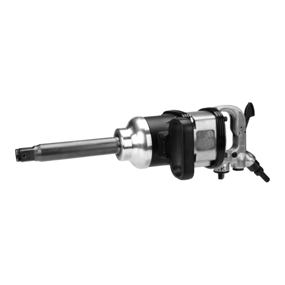
AIR IMPACT WRENCH
SET uP ANd OPERATINg INSTRuCTIONS
Visit our website at: http://www.harborfreight.com
Read this material before using this product.
Failure to do so can result in serious injury.
SAVE THIS MANuAL.
©
Copyright
2010 by Harbor Freight Tools
contained herein may be reproduced in any shape or form without the express written consent of
Harbor Freight Tools. Diagrams within this manual may not be drawn proportionally. Due to continuing
improvements, actual product may differ slightly from the product described herein. Tools required for
assembly and service may not be included.
For technical questions or replacement parts, please call 1-800-444-3353.
1" PINLESS
68128
®
. All rights reserved. No portion of this manual or any artwork
Advertisement
Table of Contents

Related Manuals for Central Pneumatic CENTRAL PNEUMATIC 68128


Summary of Contents for Central Pneumatic CENTRAL PNEUMATIC 68128
- Page 1 Harbor Freight Tools. Diagrams within this manual may not be drawn proportionally. Due to continuing improvements, actual product may differ slightly from the product described herein. Tools required for assembly and service may not be included.
-
Page 2: Important Safety Instructions
SAVE THIS MANuAL Keep this manual for the safety warn- ings and precautions, assembly, operat- ing, inspection, maintenance and cleaning procedures. Write the product’s serial number in the back of the manual near the assembly diagram (or month and year of purchase if product has no number). -
Page 3: Personal Safety
tool. Distractions are able to result in the loss of control of the tool. Personal safety Stay alert. Watch what you are do- ing and use common sense when operating the tool. Do not use the tool while tired or under the influ- ence of drugs, alcohol, or medica- tion. -
Page 4: Air Source
Store the tool when it is idle out of reach of children and other un- trained persons. A tool is dangerous in the hands of untrained users. Maintain the tool with care. properly maintained tool is easier to control. Check for misalignment or bind- ing of moving parts, breakage of parts, and any other condition that affects the tool’s operation. -
Page 5: Specific Safety Instructions
Symbol Definitions Symbol Property or statement WARNING marking concerning Risk of Eye Injury. Wear ANSI-approved eye protection. WARNING marking concerning Risk of Hearing Loss. Wear hearing protection. WARNING marking concerning Risk of Respiratory Injury. Wear NIOSH- approved dust mask/respirator. WARNING marking concerning Risk of Explosion. -
Page 6: Specifications
Wear suitable gloves to reduce the vibration effects on the user. Use tools with the lowest vibration when there is a choice. Include vibration-free periods each day of work. Grip tool with both hands as lightly as possible (while still keeping safe con- trol of it). -
Page 7: Air Supply
Air Supply TO PREVENT ExPLOSION: use only clean, dry, regulated, compressed air to power this tool. do not use oxygen, carbon dioxide, combustible gases, or any other bottled gas as a power source for this tool. Male Connector Tool Quick Coupler Valve Oiler... -
Page 8: Tool Set Up
trapped line pressure, and detach air supply hose from the air supply. Note: Residual air pressure should not be present after the tool is disconnected from the air supply. However, it is a good safety measure to attempt to discharge the tool in a safe fashion after disconnecting to ensure that the tool is disconnected and unpowered. - Page 9 For Reverse, turn the Direction Knob to the desired Reverse speed. NOTE: There are three torque settings for the Reverse direction. To loosen, set the Regulator Knob to one of the Reverse settings. Hold the Side Handle firmly and place other hand around Handle (28).
-
Page 10: User Maintenance Instructions
uSER-MAINTENANCE INSTRuCTIONS Procedures not specifically explained in this manual must be performed only by a qualified technician. TO PREVENT SERIOuS INjuRY FROM ACCIdENTAL OPERATION: Turn off tool, detach air supply, safely discharge any residual air pressure in tool, and release Trigger before performing any inspection, maintenance, or cleaning procedures. -
Page 11: Troubleshooting
Problem Possible Causes Decreased output. Not enough air pressure and/ or air flow. Obstructed trigger. Incorrect lubrication or not enough lubrication. Blocked air inlet screen (if equipped). Air leaking from loose housing, hose or connections. Mechanism contaminated. Vane wear or damage. Housing heats Incorrect lubrication or not during use. -
Page 12: Parts List
Part description Hex Screw Gasket Hammer Case Side Handle Bolt Washer Gasket Oil Seal Anvil Bushing Circlip O-Ring Anvil Hammer Bushing Hammer Hammer Cage Gasket Housing Bearing Rear End Plate Vane Rotor Cylinder Record Product’s Serial Number Here: Note: If product has no serial number, record month and year of purchase instead. Note: Some parts are listed and shown for illustration purposes only, and are not avail- able individually as replacement parts. -
Page 13: Assembly Diagram
LIMITEd 1 YEAR WARRANTY Harbor Freight Tools Co. makes every effort to assure that its products meet high quality and dura- bility standards, and warrants to the original purchaser that this product is free from defects in materials and workmanship for the period of one year from the date of purchase (90 days if used by a professional contractor or if used as rental equipment).
Need help?
Do you have a question about the CENTRAL PNEUMATIC 68128 and is the answer not in the manual?
Questions and answers