
Related Manuals for Turbo Air Smart 7


Summary of Contents for Turbo Air Smart 7
-
Page 1: Refrigeration System
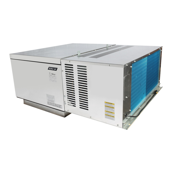
Turbo air Speeds Up the Pace of Innovation Part No. KUCST2901 Refrigeration System Installation & Operation Manual Please read this manual completely before attempting to install or operate this equipment ! Package Unit ( TOP MOUNT ) -
Page 2: Table Of Contents
CONTENTS Safety Information …………………………………… Inspection ……………………………………………… Locating SMART 7 Package Unit…………………… Installation Procedure ………………………………… Sequence of Operation ……………………………… Controller Setting …………………………………… System Troubleshooting …………………………… Electrical Wiring Diagram……………………………... -
Page 3: Safety Information
If damaged material becomes the delivering carrier’s responsibility and it should not be returned to Turbo air unless prior approval is given to do so. Check the serial tag information with invoice. Report... - Page 4 Table 1. INDOOR UNIT - Medium Temperature (Air Defrost System) Ambient 95℉ Refrigerant. Matching Plug Model Capacity BTUH Voltage MOPD NEMA Weight Fig. Supplied Ref. Receptacle (Lbs) 35℉ 38℉ STI050MR404A1 5026 5356 115/1/60 11.3 R404A 5-20R STI050MR404A2 5026 5356 208~230/1/60 R404A 6-15R STI073MR404A2...
- Page 5 Figure A. INDOOR UNIT – Medium Cabinet (Opening Size : 25 inch x 25 inch) Figure B. INDOOR UNIT – Large Cabinet (Opening Size : 25 inch x 38.5 inch) Figure C. OUTDOOR UNIT – Medium Cabinet (Opening Size : 25 inch x 25 inch) Figure D.
-
Page 6: Locating Smart 7 Package Unit
Locating SMART 7 Package Unit Unit Installation Requirements 1. You must ensure before unit placement on the roof of box that the structural strength of the box can withstand the weight of SMART7 equipment 2. The unit should be installed away from noise sensitive site and must have proper support for noise and vibration not to be transmitted into the building. - Page 7 Figure 1. Minimum Clearance at Installation of Unit. W = UNIT WIDTH W = UNIT WIDTH Figure 3. Two or more Unit Figure 2. One Unit...
-
Page 8: Installation Procedure
Installation procedure Indoor use only ( STI Model ) 1. Carefully check package for damages during transportation and unit after opening the package. 2. Requirements must be followed for installing location on the page of 6~7. 3. Ensure weights of units on the page of 4~5 and that structural strength of the box can withstand of the weight of the unit. - Page 9 Check before Unit Start-up. 1. Check all electrical and refrigerant connections. 2. Observe all applicable building and electrical codes when wiring. 3. Make sure power supply has correct voltage and phase for unit and is fused properly. 4. If unit is connected with a power cord, use the cord with plug to connect to power supply. If unit is not connected with a power cord, use hard wire to connect to power supply.
-
Page 10: Sequence Of Operation
Sequence of Operation. Operation of Refrigeration. 1. When switch is turned on, power is provided to the temperature control, compressor, condenser and evaporator fan motor. And they will run until the box temperature setting is reached. 2. When the box temperature reaches a setting, the compressor and condenser fan motors shut off while evaporator fan motor is working. -
Page 11: Controller Setting
Controller Setting. Danfoss EKC 102D Electronic Controller ( Low Temperature). The EKC 102D is used for temperature control refrigeration appliances and cold room. It contains a temperature control where the signal con be received from one temperature sensor. The sensor is placed in the cold air flow after the evaporator or in the warm air flow just before the evaporator. - Page 12 The buttons; Display The values will be shown with three digits, and with a setting you can determine whether the temperature are to be shown in ℃ or ℉. Set menu 1. Push the upper button until a parameter is shown 2.
- Page 13 Push briefly the lower button Manuel start or stop of a defrost Push the lower button for four seconds. Light emitting diode = refrigeration = defrost = fan running Cutout alarm relay / receipt alarm / see alarm code. Push briefly the upper button. If there are several alarm codes they are found in a rolling stack.
- Page 14 regulation(0), start or a manual override of the outputs can be allowed. regulation (1) 1 = regulation 0 = regulation is stopped -1 = regulation is stopped - override allowed. Stopped regulation will give a "Standby alarm". Displacement of reference The thermostat’s reference will be the setpoint plus -18 K 18 K...
- Page 15 10 degrees. Definition of Saux (S5) takes place in o69/o70. Compressor Min. ON-time Min. ON-time (in minutes) 0 min 30 min 0 min Min. OFF-time Min. OFF-time (in minutes) 0 min 30 min 4 min Compressor relay must 0: Normal function where the relay cuts in when 1 / on 0 / OFF cutin and out inversely...
- Page 16 Defrost on demand - S5 The controller will follow the effectivity of the evap- 36 K 36 K temperature’s permitted orator, and via internal calculations and measure- variation during frost ements of the S5 temperature it will be able to start a build-up.
-
Page 17: Operating Status
All the mounted sensors must be of the same type. Display step = 0.5 (normal Yes: Gives steps of 0.5° 0.1 at Pt sensor) No: Gives steps of 0.1° Case cleaning. 0=no case The status of the function can be followed here or the cleaning. - Page 18 Fault Message In an error situation the LED’s on the front will flash and the alarm relay will be activated. If you push the top button in this situation you can see the alarm report in the display. If there are several, you can continue pushing to see them.
-
Page 19: System Troubleshooting
compressor off. When the coil temperature reaches 38°F the control will terminate the defrost cycle. Room Thermostat Settings : Settings Warm position Cold position Minimum time(Sec) Maximum time (Min) Cut in [°F] Not used Cut out [°F] Not used Defrost Temperature[°F] Alarm on high temp [°F] Not used Not used... -
Page 20: Electrical Wiring Diagram
Clean drain line. Defective control. Replace defective component. Electrical Wiring Diagram. Diagram 1. Wiring diagram for SMART 7, Air Defrost 115V / 1Ph / 60Hz. Model : STI050MR404A1 Diagram 2. Wiring diagram for SMART 7, Air Defrost 208~230V / 1Ph / 60Hz. - Page 21 Model : STI050MR404A2, STX050MR404A2 Diagram 3. Wiring diagram for SMART 7, Air Defrost 208~230V / 1Ph / 60Hz. Model : STI075MR404A2, STI100MR404A2, STI130MR404A2...
- Page 22 Diagram4. Wiring diagram for SMART 7, Air Defrost 208~230V / 1Ph / 60Hz. Model : STX075MR404A2 , STX100MR404A2 , STX130MR404A2 Diagram5. Wiring diagram for SMART 7, Air Defrost 208~230V / 3Ph / 60Hz. Model : STI100MR404A3, STI130MR404A3, STX100MR404A3, STX130MR404A3...
- Page 23 Diagram6. Wiring diagram for SMART 7, Electric Defrost 208~230V / 1Ph / 60Hz. Model : STI022LR404A2, STI045LR404A2, STI055LR404A2, STI070LR404A2 Diagram7. Wiring diagram for SMART 7, Electric Defrost 208~230V / 1Ph / 60Hz. Model : STX022LR404A2, STX045LR404A2, STX055LR404A2, STX070LR404A2...
- Page 24 Diagram8. Wiring diagram for SMART 7, Electric Defrost 208~230V / 3Ph / 60Hz. Model : STI055LR404A3 , STI070LR404A3 , STX055LR404A3 , STX070LR404A3...
- Page 25 1250 Victoria street CARSON, CA 90746 TEL : 310-900-1000 FAX : 310-900-1077 Toll Free : 1-800-381-7770 1-800-627-0032 (U.S.A & Canada) http://www.turboairinc.com...
Need help?
Do you have a question about the Smart 7 and is the answer not in the manual?
Questions and answers