
Related Manuals for Turbo Air TGIM-23*


Summary of Contents for Turbo Air TGIM-23*
- Page 1 REFRIGERATOR MANUFACTURER REFRIGERATOR MANUFACTURER Turbo air MERCHANDISER SERVICE MANUAL Model No.: TGIM-23* TGIM-49*...
-
Page 2: Table Of Contents
TABLE OF CONTENTS TABLE OF CONTENTS <ICE MERCHANDISER> 1 FEATURE CHART 1. FEATURE CHART 2. PART DETAILS 3. WIRING DIAGRAM 4. SPECIFICATION OF MAIN COMPONENTS 4. SPECIFICATION OF MAIN COMPONENTS 5. MAIN PCB PROGRAMING 6. PARTS LIST 7. REPLACEMENT OF MAIN COMPONENTS 1. -
Page 3: Feature Chart
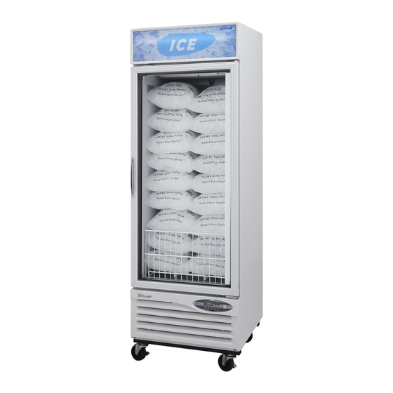
1. FEATURE CHART • Model : TGIM-23* Model : TGIM 23 <FRONT> • Model : TGIM-23* <SIDE>... -
Page 4: Feature Chart
FEATURE CHART • Model : TGIM-49* <FRONT> • Model : TGIM-49* <SIDE>... -
Page 5: Part Details
2. PART DETAILS DOOR PARTS : TGIM-23*, TGIM-49* DOOR FRAME TOP DOOR FRAME *TOP AUXILIARY DOOR FRAME A AUXILIARY DOOR FRAME *A DOOR BUSHING TOP DOOR BUSHING *TOP DOOR FRAME *LEFT DOOR GASKET BAR SPRING DOOR FRAME *BOTTOM DOOR HANDLE BAR SPRING FIXTURE DOOR FRAME *RIGHT DOOR FRAME FIXTURE- A... - Page 6 PART DETAILS ▶ DUCT(TGIM-23*) ▶ DUCT(TGIM 23 ) EVAPORATOR FAN GRILLE GUARD EVAPORATOR FRONT COVER FRONT COVER EVAPORATOR BOTTOM COVER ▶ EVAPORATOR, FAN MOTOR, DEFROST HEATER, SENSORS(TGIM-23*) EVAPORATOR FAN MOTOR & BLADE EVAPORATOR COIL THERMAL PROTECTOR DEFROST HEATER DEFROST SENSOR F-SENSOR (TEMPERATURE CONTROL)
- Page 7 PART DETAILS ▶ DUCT(TGIM-49*) ▶ DUCT(TGIM 49 ) EVAPORATOR FAN GRILLE GUARD EVAPORATOR FRONT COVER EVAPORATOR BOTTOM COVER ▶ EVAPORATOR, FAN MOTOR, DEFROST HEATER, SENSORS(TGIM-49*) EVAPORATOR FAN MOTOR & BLADE THERMAL PROTECTOR EVAPORATOR COIL DEFROST HEATER DEFROST SENSOR F-SENSOR (TEMPERATURE CONTROL)
- Page 8 PART DETAILS ▶ COMPRESSOR & FAN MOTOR(TGIM-23*) ▶ COMPRESSOR & FAN MOTOR(TGIM 23 ) COMPRESSOR CONDENSER FAN MOTOR CONDENSER ▶ COMPRESSOR & FAN MOTOR(TGIM-49*) COMPRESSOR CONDENSER FAN MOTOR FAN MOTOR CONDENSER...
-
Page 9: Wiring Diagram
3. WIRING DIAGRAM • Model : TGIM-23*... -
Page 10: Wiring Diagram
WIRING DIAGRAM • Model : TGIM-49*... -
Page 11: Specification Of Main Components
SPECIFICATION OF MAIN COMPONENTS 1. COMPRESSOR HORSE TYPE OF Current MODEL PART NAME PART NO. CAPACITY MAKER POWER MOTOR (RLA) 1,203 BTU/h TGIM-23* SK1A1C-L2W 30200Q1200 1/3 HP 3.85A SAMSUNG (303 Kcal/h) 3,200 BTU/h TGIM-49* CAJ2432Z 30200R1000 2/3 HP 7.0A TECUMSEH (807 Kcal/h) BASIC COMPRESSOR EXCHANGEABLE COMPRESSOR... -
Page 12: Main Components
MAIN COMPONENTS 4. CONDENSER FAN MOTOR MODEL PART NAME PART NO. POLE Quantity BLADE SIZE MAKER TGIM-23* IS-4420DWSG-1 39633220410 AL 4 250mm SUNG-SHIN TGIM-49* 5. EVAPORATOR FAN MOTOR MODEL PART NAME PART NO. POLE Quantity BLADE SIZE MAKER TGIM-23* IS-4420DWSN-2A 3963328120 AL 5 175mm... -
Page 13: Main Components
MAIN COMPONENTS 9. SWITCH MODEL TYPE RATING PART NO. MAKER TGIM-23* LAMP SWITCH (GREEN) 125V/20A 30281R0101 SIGNAL LUX TGIM-49* TGIM 49 POWER SWITCH (RED) POWER SWITCH (RED) 125V/20A 125V/20A 30281R0201 30281R0201 10. TRANSFORMER & MAIN PCB MODEL PART NAME SPEC PART NO. -
Page 14: Main Pcb Programing
MAIN PCB PROGRAMING 1. HOW TO USE THE DISPLAY PANEL - The default temperature setting is 16℉. - The operating temperature is between 27℉ and 5℉, which can be adjusted by using the arrow key. POWER SWITCH LAMP SWITCH TGIM-23* -. -
Page 15: Function Table
MAIN PCB PROGRAMING 2. FUNCTION TABLE Control Control Control Control Description Fucntion Objects Initial Buzzer 1. Buzzer will be sound within 2 seconds after the power is turned on. Operation 2. 88 LED displays the temperature value inside the appliance. Lamp 3. - Page 16 MAIN PCB PROGRAMING Control Control Control Control Description Fucntion Objects Turbo Compressor 6. If the 'Turbo Freeze' button is pressed under defrost mode, 88 LED Freeze Evap. Fan Motor will flash 'T.F'; however, 'Turbo Freeze' mode will start after defrost mode is Cond.
- Page 17 MAIN PCB PROGRAMING Control Control Description Fucntion Objects Defrost Heater C. Pause step Function Compressor a. To ensure that refrigeration system has the time to be stabilized, Evap. Fan Motor please allow compressor and fan motors to have enough rest time after Cond.
- Page 18 MAIN PCB PROGRAMING 3. FUNCTION MODE(Manual defrost, Error display, Model change. etc.) 3-1) Enter the Function mode ▶ Press the both up/down (or +/-) buttons at the same time for 5 seconds. 88 LED display "SL". 3-2) Manual Defrost Mode ▶...
- Page 19 MAIN PCB PROGRAMING Code Content Perception Method Freezer Operation State -. Sensor shorted. -. The compressor runs for 30 minutes and F-sensor Malfunction -. Sensor disconnected. stops for 5 minutes repeatedly. -. Defrost heater may operate it. -. Sensor shorted -.
-
Page 20: Parts List
6. PARTS LIST Model Part Name Part Number Description TGIM TGIM ADJUSTABLE FEET BOLT ADJUSTABLE FEET BOLT 30206K0100 1/2" 28mm Compressor Compressor 30200Q1200 SK1A1C-L2W(115V/60Hz) Compressor Compressor 30200R1000 30200R1000 CAJ2432Z CAJ2432Z Compressor Relay J531Q34E22OM3503 Compressor Overload 4TM 795TFBZZ-53 Compressor Run Capacitor 30264L0100 250V/12 ㎌... - Page 21 PARTS LIST Model Model Part Name Part Number Description TGIM TGIM Evaporator Sensor 30227Q1210 F-D Sensor Evaporator Thermal Fuse 30272L0401 PST-3(80℃/10℃) Evaporator Defrost Heater 30228L0803 30228L0803 445W(Sh 445W(Sheath Heater) th H Evaporator Defrost Heater 30228L0701 600W(Sheath Heater) Evaporator Drain Pan Heater 30228L1400 Evaporator Drain Pan Heater 30228L1500...
- Page 22 PARTS LIST Model Part Name Part Number Description TGIM TGIM Sign Panel P0145A1200 Sign Panel P0145A1300 Sign Frame *Left 30222A2400 Sign Frame *Right 30222A2500 Sign Frame *Left 30222R2200 Sign Frame *Right 30222R2300 Bottom Grille Bottom Grill Bottom Grill 30224R0103 30224R0103 Bottom Grill 30200R3400 White Painting...
-
Page 23: Replacement Of Main Components
7. REPLACEMENT OF MAIN COMPONENTS 1. TGIM-23* 1-1. BOTTOM GRILLE PARTS - MAIN PCB, TRANSFORMER, POWER RELAY - DISPLAY PCB - LAMP SWITCH, POWER SWITCH A. Remove the 4 screws and detach the bottom grille. B. Remove the Bracket of Display PCB... - Page 24 REPLACEMENT OF MAIN COMPONENTS C . Remove the Electrical Box Cover.
- Page 25 REPLACEMENT OF MAIN COMPONENTS D. Replace the Main PCB, Transformer, and Magnetic contactor. E. Replace the SMPS -. LED ballast (SMPS) is located on the other side of the main PCB base.
- Page 26 REPLACEMENT OF MAIN COMPONENTS 1 2 REPLACE THE DOOR 1-2 REPLACE THE DOOR A. Disassemble bottom grille as described section 7-1, A,B,C,D B. Disconnect the door heater and lamp wire. C. Remove the Sign Frame(Left, Right) by unscrewing the four screws of each side.
- Page 27 REPLACEMENT OF MAIN COMPONENTS D. Pull out sign panel to the Right side. E. Remove the bottom sign panel frame. - Replace the Ballast (Sign Panel)
- Page 28 REPLACEMENT OF MAIN COMPONENTS F. Remove the harness of door switch. - Replace door Switch. G. Remove the top hinge. H. Lift up the door and pull out the heater wire at the same time.
- Page 29 REPLACEMENT OF MAIN COMPONENTS 2. TGIM-49* 2-1. BOTTOM GRILL PARTS - Condensing Unit, Ballast. Power Relay A. Remove Bottom Grill by unscrewing the four screws. B. Disconnect Connector to replace the condensing unit.
- Page 30 REPLACEMENT OF MAIN COMPONENTS C. Remove two screws from the base of condensing unit. 1. Pull out the Condensing Unit. 2. Replace the Parts. D. Slide out the Condensing Unit to replace the fan motor and the compressor.
- Page 31 REPLACEMENT OF MAIN COMPONENTS E. Remove one screw from each side and remove the wire junction box cover. * Replace the magnetic contactor. F. Disconnect connector to replace the SMPS...
- Page 32 REPLACEMENT OF MAIN COMPONENTS G. Replace the SMPS...
- Page 33 REPLACEMENT OF MAIN COMPONENTS 2-2. Parts inside the top sign panel - PCB, TRANSFORMER. BALLAST, POWER SWITCH, LAMP SWITCH Remove two screws from the side bracket. B. Slide out the sign panel. - Replace the parts...
- Page 34 REPLACEMENT OF MAIN COMPONENTS Remove the display panel. D. Replace parts as needed (Display board, Power switch, Lamp switch)
- Page 35 REPLACEMENT OF MAIN COMPONENTS 2-3. Replace the Door Disconnect the door heater wire in the wire junction box. B. Remove the top hinge. C. Lift up the door and pull out the heater wire at the same time..
Need help?
Do you have a question about the TGIM-23* and is the answer not in the manual?
Questions and answers