Table of Contents
Advertisement
Mainboard User's Manual
This publication, including photographs, illustrations and software,
is under the protection of international copyright laws, with all
rights reserved. Neither this manual, nor any of the material
contained herein, may be reproduced without the express written
consent of the manufacturer.
The information in this document is subject to change without
notice. The manufacturer makes no representations or warranties
with respect to the contents hereof and specifically disclaims any
implied warranties of merchantability or fitness for any particular
purpose. Further, the manufacturer reserves the right to revise this
publication and to make changes from time to time in the content
hereof without obligation of the manufacturer to notify any person
of such revision or changes.
Trademarks
IBM, VGA, and PS/2 are registered trademarks of International
Business Machines.
Intel, Pentium, Pentium-II, Pentium-III, Pentium 4, MMX,
Celeron and Tualatin are registered trademarks of Intel
Corporation.
Microsoft, MS-DOS and Windows 98/ME/NT/2000/XP are
registered trademarks of Microsoft Corporation.
PC-cillin is a trademark of Trend Micro Inc.
AMI is a trademark of American Megatrends Inc.
MediaRing Talk is a registered trademark of MediaRing Inc.
3Deep is a registered trade mark of E -Color Inc.
It has been acknowledged that all mentioned brands or product
names are trademarks or registered trademarks of their respective
holders.
Copyright © 2003
All Rights Reserved
MS9158 Series, V5.0A
P4M266A/February 2003
Advertisement
Table of Contents

Related Manuals for MATSONIC MS9158 Series


Summary of Contents for MATSONIC MS9158 Series
- Page 1 3Deep is a registered trade mark of E -Color Inc. It has been acknowledged that all mentioned brands or product names are trademarks or registered trademarks of their respective holders. Copyright © 2003 All Rights Reserved MS9158 Series, V5.0A P4M266A/February 2003...
- Page 2 Mainboard User’s Manual Notice: 1. Owing to Microsoft’s certifying schedule is various to every supplier, we might have some drivers not certified yet by Microsoft. Therefore, it might happen under Windows XP that a dialogue box (shown as below) pop out warning you this software has not passed Windows Logo testing to verify its compatibility with Windows XP.
-
Page 3: Table Of Contents
Mainboard User’s Manual Table of Contents Chapter 1: Introduction .............. 1 Key Features..............2 Package Contents ...............6 Static Electricity Precautions..........7 Pre-Installation Inspection...........7 Chapter 2: Mainboard Installation ..........9 Mainboard Components............10 I/O Ports................11 Installing the Processor.............12 Installing Memory Modules ..........13 Jumper Settings ..............15 The Pane l Connectors............ - Page 4 Mainboard User’s Manual...
-
Page 5: Chapter 1: Introduction
1: Introduction Chapter 1 Introduction This mainboard has a Socket 478 for the Intel Pentium 4 type of processors supporting front side bus (FSB) speeds up to 400/533 MHz. This mainboard has the VIA P4M266/A Northbridge and VT8235 Southbridge chipsets that support AC 97 audio codec, and provide Ultra DMA 33/66/100/133 function. -
Page 6: Key Features
Mainboard User’s Manual Key Features This mainboard has these key features: Socket 478 Processor The PGA Socket 478 Accommodates Intel Pentium 4 CPUs Supports a front-side bus (FSB) of 400/533 MHz Chipset There are VIA P4M266/A Northbridge and VT8235 Southbridge in this chipset in accordance with an innovative and scalable architecture with proven reliability and performance. - Page 7 1: Introduction Built-in Graphics System P4M266/A integrates S3 ’s Savag8 graphics accelerator into a single chip. P4M266/A brings mainstream graphics performance to the Value PC with leading-edge 2D, 3D and DVD video acceleration into a cost effective package. Based on its capabilities, P4M266/A is an ideal solution for the consumer, corporate mobile users and entry level professionals.
- Page 8 Mainboard User’s Manual Expansion Options The mainboard comes with the following expansion options: Two 32-bit PCI slots capable of Ultra DMA bus mastering with transfer rates of 33/66/100/133 MB/sec An 4xAGP slot A CNR (Communications and Networking Riser) slot Onboard I/O Ports The mainboard has a full set of I/O ports and connectors: Two PS/2 ports for mouse and keyboard One serial port...
- Page 9 1: Introduction Root hub consists 4 downstream facing ports with integrated physical layer transceivers shared by UHCI and EHCI Host Controller Support PCI-Bus Power Management I nterface Specification release 1.1 Legacy support for all downstream facing ports Built-in Ethernet LAN (Optional) 100Base-TX/10Base-T Physical Layer Solution Dual Speed –...
-
Page 10: Package Contents
Mainboard User’s Manual Package Contents Attention: This mainboard serial has two models, MS9158D (with LAN) and MS9158E (without LAN). Please contact your local supplier for more information about your purchased model. Each model will support different specification listed as below: Model Specification MS9158D... -
Page 11: Static Electricity Precautions
1: Introduction Static Electricity Precautions Static electricity could damage components on this mainboard. Take the following precautions while unpacking this mainboard and installing it in a system. 1. Don’t take this mainboard and components out of their original static-proof package until you are ready to install them. 2. - Page 12 Mainboard User’s Manual...
-
Page 13: Chapter 2: Mainboard Installation
2: Mainboard Installation Chapter 2 Mainboard Installation To install this mainboard in a system, please follow these instructions in this chapter: Identify the mainboard components Install a CPU Install one or more system memory modules Make sure all jumpers and switches are set correctly Install this mainboard in a system chassis (case) Connect any extension brackets or cables to connecting headers on the mainboard... -
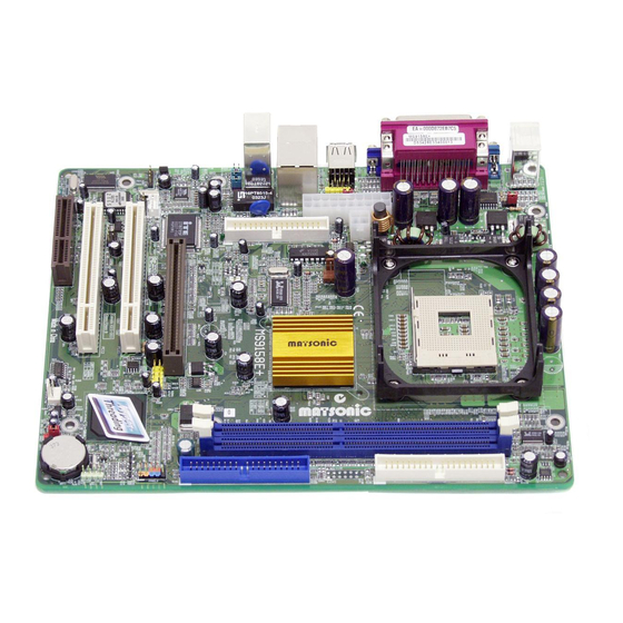
Page 14: Mainboard Components
Mainboard User’s Manual Mainboard Components Identify major components on the mainboard via this diagram underneath. Note: Those jumpers of mainboard not appearing in this illustration are for testing only. -
Page 15: I/O Ports
2: Mainboard Installation I/O Ports The illustration below shows a side view of the built-in I/O ports on the mainboard. (only for MS9158E) Use the upper PS/2 port to connect a PS/2 PS/2 Mouse pointing device. Use the lower PS/2 port to connect a PS/2 PS/2 Keyboard keyboard. -
Page 16: Installing The Processor
Mainboard User’s Manual Installing the Processor This mainboard has a Socket 478 processor socket. When choosing a processor, consider the performance requirements of the system. Performance is based on the processor design, the clock speed and system bus frequency of the processor, and the quantity of internal cache memory and external cache me mory. -
Page 17: Installing Memory Modules
2: Mainboard Installation Installing Memory Modules This mainboard accommodates two 168-pin 3.3V unbuffered Synchronous Dynamic Random Access Memory (SDRAM) and Double Data Rate SDRAM ( two 184-pin 2.5V unbuffered SDRAM) Dual Inline Memory Module (DIMM) sockets, supporting 133 MHz SDRAM / 266 MHz DDR SDRAM. The SDRAM DIMMs and DDRs can synchronously work with 100 MHz or operates over a 266 MHz system bus. - Page 18 Mainboard User’s Manual Installation Procedure The mainboard accommodates two types of memory modules. You must install at least one module in any of these sockets. You can install each module up to 2GB system memory. Refer to the following to install the memory modules. 1.
-
Page 19: Jumper Settings
2: Mainboard Installation Jumper Settings PANEL1 JP1A1 JP1B1 PANEL2 JBAT1 JBAT1: Clear CMOS Jumper This jumper is to clear the contents of CMOS memory. You may need to clear the CMOS memory if the settings in the Setup Utility are incorrect that prevents your mainboard from operating. To clear the CMOS memory, disconnect all the power cables from the mainboard and then move the jumper cap into the CLEAR setting for a few seconds. - Page 20 Mainboard User’s Manual JP1: DRAM Voltage (VCC) This jumper enables to select voltage of DRAM. Function Jumper Setting 2.5V (DDR) Open Pins 1-2 (SDR) Short Pins 1-2 J2A/B/C/D, J3A/B/C/D: DDR/SDR DRAM Type Selector This jumper enables to select the type of DDR or SDR DRAM.
-
Page 21: The Pane L Connectors
2: Mainboard Installation The Panel Connector PANEL1 If there are a headphone jack or/and a microphone jack on the front panel, connect the cables to the PANEL1 on the mainboard. Device Pins Line Out (L) 9, 10 Line Out(L) Line Out(L) (Pin 9) (Pin 10) Empty... - Page 22 Mainboard User’s Manual J16: LAN LED Indicator This connector is attached to LAN device that needs a LED indicator. Device Pins Link LED 1, +2 LINK ACT LED +3, 4 Note: The plus sign (+) indicates a pin which must be connected to a positive voltage.
-
Page 23: Other Devices Installation
2: Mainboard Installation Other Devices Installation Floppy Diskette Drive Installation The mainboard has a floppy diskette drive (FDD) interface and ships with a diskette drive ribbon cable that supports one or two floppy diskette drives. You can install a 5.25-inch drive and a 3.5- inch drive with various capacities. -
Page 24: Expansion Slots Installation
Mainboard User’s Manual Expansion Slots Installation This mainboard has one 4xAGP, one CNR and two 32-bit PCI (Peripheral Components Interconnect) expansion slots. 4 x AGP (Accelerated Graphics Port) Slot You can install a graphics adapter supporting 4xAGP specification in the AGP slot. This slot has one 4xAGP edge connector. CNR (Communications Networking Riser) Slot You can install a CNR (the Communications Networking Riser) card in the CNR slot. -
Page 25: Connecting Optional Devices
2: Mainboard Installation Connecting Optional Devices Refer to the following for information on connecting the mainboard’s optional devices: CD2 CD1 SIR1 WOM1 WOL1 SPK1 USB2... - Page 26 Mainboard User’s Manual J12: Sleep Switch This header is connected to the sleep button for suspending the computer’s activity if pushing the button. Or, the computer is automatically suspended after passing a period of time. Signal -EXTSMI SPK1: Speaker Connector Connect the cable from the PC speaker to the SPK1 header on the mainboard.
- Page 27 2: Mainboard Installation If you have installed a modem, use the cable provided with the modem to plug into the mainboard WOM1 connector. This enables the Wake On Modem (WOM1) feature. When your system is in a power-saving mode, any modem signal automatically resumes the system.
- Page 28 Mainboard User’s Manual SIR1: Serial infrared port The mainboard supports a Serial Infrared (SIR1) data port. Infrared ports allow the wireless exchange of information between your computer and similarly equipped devices such as printers, laptops, Personal Digital Assistants (PDAs), and other computers. Signal Signal IRTX...
-
Page 29: Chapter 3: Bios Setup Utility
3: BIOS Setup Utility Chapter 3 BIOS Setup Utility Introduction The BIOS Setup Utility records settings and information of your computer, such as date and time, the type of hardware installed, and various configuration settings. Your computer applies those information to initialize all the components when booting up and basic functions of coordination between system components. -
Page 30: Running The Setup Utility
Mainboard User’s Manual Running the Setup Utility Every time you start your computer, a message appears on the screen before the operating system loading that prompts you to “Hit <DEL>if you want to run SETUP”. Whenever you see this message, press the Delete key, and the Main menu page of the Setup Utility appears on your monitor. -
Page 31: Standard Cmos Setup Page
3: BIOS Setup Utility Standard CMOS Setup Page This page helps you set up basic information such as the date and time, the IDE devices, and the diskette drives. AMIBIOS SETUP – STANDARD CMOS SETUP (C) 2000 American Megatrends, Inc. All Rights Reserved Date (mm/dd/yy) : Tue Jan 21, 2003 Time (hh/mm/ss) : 11:44:33 32Bit... -
Page 32: Advanced Setup Page
Mainboard User’s Manual Advanced Setup Page This page sets up more advanced information about your system. Be more careful to this page. Any changes can affect the operation of your computer. AMIBIOS SETUP – ADVANCED SETUP (C) 2000 American Megatrends, Inc. All Rights Reserved Quick Boot Enabled AGP Aperture Size... - Page 33 3: BIOS Setup Utility Enable this item if any IDE hard disks S.M.A.R.T. for support the S.M.A.R.T. (Self- Hard Disks Monitoring, Analysis and Reporting Technology) feature. This item determines if the Num Lock BootUp Num- key is active or inactive at system start- Lock up time.
- Page 34 Mainboard User’s Manual This item determines the operation of SDRAM CAS# SDRAM memory CAS (column address Latency strobe). It is recommended that you leave this item at the default value. The 2T setting requires faster memory that specifically supports this mode. Enable this item to increase SDRAM SDRAM Bank memory speed.
-
Page 35: Power Management Setup Page
3: BIOS Setup Utility If your P4 CPU is not HT CPU, this item Hyper Threading will be hidden. Function If your P4 CPU is HT CPU, BIOS will show this item. You can set "Disabled" or "Enabled" to control HT CPU support in O.S. - Page 36 Mainboard User’s Manual This sets the timeout for Suspend mode in Suspend Time minutes. If the time selected passes without any system activity, the computer will enter power-saving Suspend mode. This item sets up the timeout to power down Hard Disk the hard disk drive, if there is no hard disk Time Out activity after passing the preset period of...
-
Page 37: Pci/Plug And Play Setup Page
3: BIOS Setup Utility PCI / Plug and Play Setup Page This page sets up some parameters for devices installed on the PCI bus and those utilizing the system plug and play capability. AMIBIOS SETUP – PCI / PLUG AND PLAY SETUP (C) 2000 American Megatrends, Inc. -
Page 38: Load Optimal Settings
Mainboard User’s Manual Load Optimal Settings If you select this item and press Enter a dialog box appears. If you press Y, and then Enter, the Setup Utility loads a set of fail-safe default values. These default values are not very demanding and they should allow your system to function with most kinds of hardware and memory chips. - Page 39 3: BIOS Setup Utility Use this item to enable or disable the OnBoard FDC onboard floppy disk drive interface. Use this item to enable or disable the OnBoard Serial onboard COM1 serial port, and to assign a PortA port address. Use this item to enable or disable the OnBoard IR onboard infrared port, and to assign a port...
-
Page 40: Cpu Pnp Setup Page
Mainboard User’s Manual This item allows you to enable the USB USB Device device, if you have installed a USB device Legacy on the system board. Support Enable this item to make a small portion of ThumbDrive memory storage device for the USB ports. Support For CPU PnP Setup Page This page helps you manually configure the mainboard for the... -
Page 41: Hardware Monitor Page
3: BIOS Setup Utility Hardware Monitor Page This page sets up some parameters for the hardware monitoring function of this mainboard. AMIBIOS SETUP – HARDWARE MONITOR (C) 2000 American Megatrends, Inc. All Rights Reserved *** System Hardware *** Vcore 1.632V Vcc 2.5V 2.496V Vcc 3.3V... -
Page 42: Exit
Mainboard User’s Manual Exit Highlight this item and press Enter to save the changes that you have made in the Setup Utility configuration and exit the program. When the Save and Exit dialog box appears, press Y to save and exit, or press N to exit without saving. -
Page 43: Chapter 4: About The Software & Cd -Rom
4: About the Software & CD -ROM Chapter 4 About the Software & CD-ROM The support software CD-ROM that is included in the mainboard package contains all the drivers and utility programs needed to properly run the bundled products. Below you can find a brief description of each software program, and the location for your mainboard version. -
Page 44: Utility Software Reference
Mainboard User’s Manual Utility Software Reference All the utility software available on the CD-ROM is Windows compliant. It is provided only for the convenience of customers. The following software is furnished under license and may only be used or copied in accordance with the terms of the license. Note: The software in these folders is subject to change at anytime without prior notice. - Page 45 4: About the Software & CD-ROM MediaRing Talk – Telephony Software To install the MediaRing Talk voice modem software for the built- in modem, run MRTALK-SETUP72.EXE from the following directory: \UTILITY\MEDIARING TALK Super Voice – Fax/Modem Software To install the Super Voice voice, fax, data communication application for use with the built- in fax/modem, run PICSHELL.EXE from the following directory: \UTILITY\SUPER VOICE...
Need help?
Do you have a question about the MS9158 Series and is the answer not in the manual?
Questions and answers