Advertisement
Available languages
Available languages
Quick Links
Download this manual
See also:
Use and Care Manual
INSTALLATIONINSTRUCTIONS
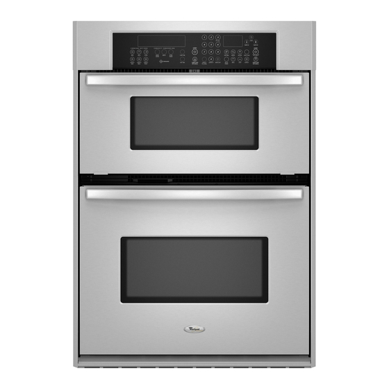
27" (68.6 CM) AND 30" (76.2 CM) ELECTRICBUILT-IN
MICROWAVE/OVEN COMBINATION
INSTRUCTIONSD'INSTALLATION DE L'ENSEMBLE FOURA
MICRO-ONDES ETFOUR CONVENTIONNEL
e=
e=
ELECTRIQUES ENCASTRESDE 27" (68,6 CM) ET
30" (76,2 CM)
Table of Contents/Table
des mati_res
BUILT-IN MICROWAVE/OVEN
COMBINATION
SAFETY ...................... 1
INSTALLATION
REQUIREMENTS
...........................................................
2
Tools and Parts .......................................................................................
2
Built-In Microwave/Oven
Combination
Location Requirements
........... 2
Electrical Requirements ..........................................................................
3
INSTALLATION
INSTRUCTIONS
.............................................................
4
Prepare Built-In Microwave/Oven
Combination
.................................... 4
Remove Oven Door ................................................................................
4
Remove Oven Trim .................................................................................
4
Make Electrical Connection ....................................................................
4
Install Oven .............................................................................................
5
Complete Installation ..............................................................................
6
SI_CURITI_ DE L'ENSEMBLE
FOUR .&
MICRO-ONDES
ET FOUR CONVENTIONNEL
ENCASTRI_S ................ 7
EXIGENCES D'INSTALLATION ................................................................
7
Outillage et pieces ..................................................................................
7
Exigences d'emplacement
de I'ensemble four &
micro-ondes
et four conventionnel
encastres .......................................
7
Specifications
electriques .......................................................................
8
INSTRUCTIONS
D'INSTALLATION
.........................................................
9
Preparation de I'ensemble four a micro-ondes
et
four conventionnel
encastres .................................................................
9
D_pose de la porte du four .....................................................................
9
D_pose de la garniture du four ...............................................................
9
Raccordement
electrique .....................................................................
10
Installation du four ................................................................................
11
Achever I'installation .............................................................................
12
BUILT-INMICROWAVE/OVEN COMBINATION SAFETY
Your safety and the safety of others are very important.
We have provided
many important
safety
messages
in this manual
and on your appliance.
Always
read and obey all safety
messages.
This is the safety alert symbol.
This symbol alerts you to potential hazards that can kill or hurt you and others.
All safety messages will follow the safety alert symbol and either the word "DANGER" or "WARNING."
These words mean:
You can be killed or seriously injured if you don't immediately
follow
instructions.
You can be killed or seriously injured if you don't follow
instructions.
All safety messages will tell you what the potential hazard is, tell you how to reduce the chance of injury, and tell you what can
happen if the instructions are not followed.
iMPORTANT:
Save for local electrical
inspector's
use.
iMPORTANT
:
A, conserver
pour consultation
par I'inspecteur
local des installations
61ectriques.
W10192051A
Advertisement

Related Manuals for Maytag MMW7530WDS01


Summary of Contents for Maytag MMW7530WDS01
- Page 1 INSTALLATIONINSTRUCTIONS 27" (68.6 CM) AND 30" (76.2 CM) ELECTRICBUILT-IN MICROWAVE/OVEN COMBINATION INSTRUCTIONS D'INSTALLATION DE L'ENSEMBLE FOURA MICRO-ONDES ETFOUR CONVENTIONNEL ELECTRIQUES ENCASTRESDE 27" (68,6 CM) ET 30" (76,2 CM) Table of Contents/Table des mati_res SI_CURITI_ DE L'ENSEMBLE FOUR .& BUILT-IN MICROWAVE/OVEN COMBINATION SAFETY ......
- Page 2 INSTALLATIONREQUIREMENTS Product Dimensions Yoos @s,d Gather the required tools and parts before starting installation. 27" (68.6 cm) and 30" (76.2 cm) Ovens Read and follow the instructions provided with any tools listed here. Tools needed • Phillips screwdriver • Measuring tape •...
- Page 3 Cabinet Dimensions If codes permit and a separate ground wire is used, it is 27" (68.6 cm) and 30" (76.2 cm) Ovens recommended that a qualified electrical installer determine that the ground path and wire gauge are in accordance with local codes.
- Page 4 Ifthehouse h asaluminum w iring follow theprocedure below: 2. Connect thealuminum w iring totheadded section o f copper wire using special connectors and/or tools 1. Connect asection o fsolid copper wire tothepigtail designed andULlisted forjoining c opper toaluminum. leads. Follow theelectrical connector manufacturer's recommended procedure.
- Page 5 4. Install aULlisted orCSA approved conduit connector tothe 5. Connect the green (or bare) ground wire (H) from the oven junction b ox. cable to the green (or bare) ground wire (in the junction box) using a UL listed wire connector. 6.
- Page 6 Push against seal area of front frame to push oven completely into cabinet and center oven into cabinet cutout. A. Push trim into place and replace screw. 3. On models with shipping feet, use a Phillips screwdriver to remove screws attaching the shipping feet. 9.
- Page 7 4. Press START. Microwave oven should begin cooking, and the If you need Assistance or Service: microwave oven interior light should be on. Please reference the "Assistance or Service" section of the Use Let microwave oven complete cooking time. A tone will sound and Care Guide or contact the dealer from whom you purchased 4 times at the end of the cooking time, and the microwave your built-in and microwave ovens.
- Page 8 Vue lat_rale du placard Dimensions du produit Fours de 27" (68,6 cm) et 30" (76,2 cm) A. Profondeur de I'ouverture 23¼" (59,1 cm) min. B. Profondeur du four encastr_ 23" (58,4 cm) C. Fagade du four D. Four encastr_ E. Placard Si on utilise un conducteur distinct de liaison &...
- Page 9 • L'installateur doit fournir un connecteur de conduit Un modele de 7,3 & 9,6 kW/240 volts (5,5 a 7,2 kW/208 volts) doit _tre alimente par un circuit independant de 40 A. Un (homologation UL ou CSA). modele de 7,2 kW ou moins a 240 volts (5,4 kW ou moins •...
- Page 10 Tableau des options de raccordement _lectrique C&blage de la maison : Voir la section : 4 conducteurs C&ble & 4 conducteurs depuis le point de distribution du domicile Risque de choc _lectrique D_connecter la source de courant _lectrique avant I'entretien. 3 conducteurs C&ble &...
- Page 11 Pousser contre la zone du joint du ch£ssis avant pour introduire completement le four dans le placard et centrer le C&ble _ 3 conducteurs depuis le point de distribution domicile - I_.-U. seulement four dans I'ouverture. IMPORTANT : Utiliser le c&ble & 3 conducteurs depuis le point de distribution du domicile Iorsque les codes Iocaux autorisent un tel raccordement.
- Page 12 Faire glisser I'extremit6 superieure de chaque tringle de 9. Utiliser les vis &t_te plate n° 8-18 x 3/8"fournies dans le sachet garniture, vers le haut, dans les rails lateraux du four. de vis, pour fixer chaque piece de garniture sur le four. 10.
Need help?
Do you have a question about the MMW7530WDS01 and is the answer not in the manual?
Questions and answers