Maytag MMW5530DAB Installation Instructions Manual
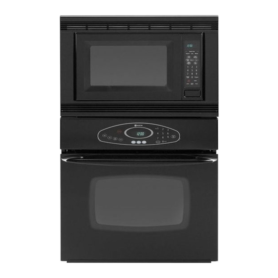
Built-in 30" electric combination wall ovens
Hide thumbs
Also See for MMW5530DAB:
- Installation instructions manual (7 pages) ,
- Use and care manual (68 pages)
Advertisement
Available languages
Available languages
Quick Links
Download this manual
See also:
Use and Care Manual
il_il
r,__ i iE_i[o
il_
ii." !_ii[o]_
Built-In 30" Electric
Combination Wall Ovens
403 WEST FOURTH STREET, NORTH
|
J
NEWTON, IA 50208
COMBINATION
WALLOVEN
CUTOUT
DIMENSIONS
in
cm
A
30 MIN
76.20
MIN
B
24 MIN
60.96
MIN
C
47 + 1/16
119.38
+.16
D
24 MIN
60.96
E
28-1/2 + 1/16
72.39
+ .16
F
47-5/8
120.97
G
29-3/4
75.57
H
24-7/16
62.07
I
4 to 20
10.2 to 50.8
* Hole must be cut as close to corner
of cabinet
as possible.
Do not block air intake slots along bottom
of oven.
C
•r'--D _.._
1
I
v
!
INSTALLATION
1. Cut hole in cabinet to mount oven. Cutout in
cabinet should be level and straight.
NOTE: There are no provisions to level the unit
after it is installed. An oven that is not level could
cause poor baking results.
2. Install plywood floor as shown above.
3. Attach unit to the cabinet with 4 No. 8" flat head
screws supplied inside of envelope containing
these instructions. Pre-drill holes in cabinet for
attachment screws using 1/8" drill. Oven
mounting holes are provided in side trim.
4. See instructions "Electrical Connections" for
electrical hook-up.
5. See figure 1 for lower trim installation.
6. See User's Manual for operating instructions.
FIGURE 1
Remove lower screws from hinge receptacle plates. Align
lower trim and reinstall screws.
NOTE: Lower trim overlaps front edge of cabinet by 9/16".
CAUTION
For European style cabinets (flush front) the required clearance for operation of the oven door is minimum
spacing of 7/8" between the cutout and the door, hinge or drawer of the cabinet.
Some built-in cabinets may not be wide enough, due to their construction,
to allow this installation.
8101 P565-60
(07-03-00)
Advertisement

Related Manuals for Maytag MMW5530DAB


Summary of Contents for Maytag MMW5530DAB
- Page 1 Built-In 30" Electric 403 WEST FOURTH STREET, NORTH il_il r,__ i iE_i[o Combination Wall Ovens ii." !_ii[o]_ NEWTON, IA 50208 COMBINATION WALLOVEN CUTOUT DIMENSIONS 30 MIN 76.20 24 MIN 60.96 •r'--D _.._ 47 + 1/16 119.38 +.16 24 MIN 60.96 28-1/2 + 1/16 72.39 + .16...
- Page 2 ELECTRICAL CONNECTIONS Unit to be properly circuit protected and wired according to local electrical code and National Electrical Code. It is advisable that the electrical wiring and hookup be Improper installation of the grounding accomplished by a competent electrician. circuit can result in a risk of electric 120/240 VAC or 120/208 VAC 60 Hz.
- Page 3 Hornos electricos 403 WEST FOURTH STREET, NORTH empotrados de pared NEWTON, IA 50208 combinados de 30" CORTE COMBINADO DEL HORNO DE PARED DIMENSIONES pulgadas 76.20 24 MiN 60.96 _r'-D _...= 47 + 1/16 119.38 +.16 60.96 MiN 28-1/2 + 1/16 72.39 + .16 47-5t8...
- Page 4 CONEXIONES ELI_CTRICAS El circuito de la unidad debe estar protegido y cableado ADVERTENCIA correctamente y de acuerdo con los c6digos electricos locales y con el C6digo Electrico Nacional. instalacion incorrecta del circuito Es recomendable que el cableado y las conexiones electricas las realice un electricista competente.
-
Page 5: Mise En Service
Fours electriques mixtes 403 WEST FOURTH STREET, NORTH "_ encastres de 30 po DECOUPE POUR LE FOUR ENCASTRE MIXTE ,, B O '_ I| Ol" " I "0 i 1n Orifice d'acces de conduit de 1 1/4 pode diamctre* "_"_B---= 2 ! Plancherencontreplaqu_ de 5/8 po (doitpouvoirsupporter250Ib) DIMENSIONS 30 MIN. -
Page 6: Entretien
RACCORDEMENT A L'¢:LECTRICIT¢: Le circuit utilise par I'appareil doit 6tre correctement AVE RTISS EMENT protege et c_ble conformement au code d'electricite local et au << National Electrical Code >>. mauvaise realisation de la mise a la II est recommande que le c_blage et le raccordement electrique soient effectues par un electricien competent.
Need help?
Do you have a question about the MMW5530DAB and is the answer not in the manual?
Questions and answers