Coleman DGAA Installation Manual
High efficiency sealed combustion gas furnace (single stage downflow only) 56-90 mbh input (16.41 -26.38 kw)input
Hide thumbs
Also See for DGAA:
- User's information manual (15 pages) ,
- User's information, maintenance and service manual (14 pages)
Table of Contents
Advertisement
.........................................
14
', H',
,'1.-¢" 'l.I
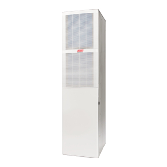
HIGH EFFICIENCY
SEALED COMBUSTION
GAS FURNACE
MODELS:
DGAA and DGAH
(Single Stage Downflow
Only)
56-90
MBH INPUT
(16.41 -26.38 KW)INPUT
ISO
9OOl
Certified
Quality
Management
System
For Installation
In:
1.
Manufactured
(Mobile) Homes
2.
Recreational
Vehicles & Park Models
3.
Modular Homes & Buildings
!
I
LIST OF SECTIONS
SAFETY
................................................
1
DUCTWORK
............................................
4
RETURN AIR REQUIREMENTS
.............................
8
FI LTE RS ...............................................
9
GAS LINE INSTALLATION
.................................
9
ELECTRICAL
POWER
..................................
12
ROOF JACK VENT/COMBUSTION
AIR SYSTEM
.............
13
SAFETY CONTROLS
...................................
20
START-UP AND ADJUSTMENTS
..........................
20
WIRING DIAGRAM
.....................................
26
LIST OF FIGURES
Furnace Dimensions
......................................
4
Air Distribution Systems
....................................
5
Closet To Door Clearance - 5" or Greater
......................
5
Furnace To Closet Door Clearance - 1" To 5" . ..................
6
Furnace To Closet Door Clearance - Less Than 1" . ..............
6
Duct Connector Dimensions
................................
6
Recommended
Floor Cut-out ................................
7
Duct Connector Depth .....................................
7
Duct Connector Screw Attachment
...........................
7
Duct Connector Tab Attachment
.............................
7
Anti-Backflow
Damper
.....................................
8
Floor Installation
..........................................
8
Furnace Air Filters
........................................
9
Gas Piping
.............................................
10
Burner Assembly
........................................
10
Line Wiring Connections
..................................
12
Wiring for Heat Only Thermostat
............................
13
Wiring for Electronic Heat-Cool Thermostat
...................
13
Wiring for Standard Heat-Cool Thermostat
...................
13
Wiring for Blend Air Accessory
.............................
13
Standard Roof Jack
.....................................
15
Roof Jack With Removable
Crowns .........................
16
Roof Jack
.............................................
17
Connecting
Roof Jack to Furnace
..........................
17
Roof Jack Assembly
.....................................
18
Ceiling Rings ...........................................
18
Home Layout
..........................................
19
Pressure Switch Tubing Routing
...........................
20
Gas Valve
.............................................
23
Reading Gas Pressure
...................................
24
Furnace Control Board ...................................
24
Wiring Diagram - DGAA ..................................
26
Wiring Diagram - DGAH ..................................
27
LIST OF TABLES
Unit Clearances
to Combustibles
.............................
4
Roof Jack Options
......................................
18
External Static Pressure Range ..............................
8
Inlet Gas Pressure Range
................................
23
Filter Sizes - All Models
....................................
9
Nominal Manifold Pressure ................................
23
High Altitude Duration Chart
...............................
12
Blower Performance
CFM - Downflow Without Filters ...........
25
Ratings & Physical / Electrical Data ..........................
13
AC Accessories
........................................
25
SECTION
I: SAFETY
[_
This is a safety alert symbol. When you see this symbol on
labels or in manuals,
be alert to the potential
for personal
injury.
Understand
and pay particular attention to the signal words DANGER,
WARNING, or CAUTION.
DANGER
indicates
an imminently
hazardous
situation, which, if not
avoided, will result in death or serious
iniurv.
WARNING
indicates
a potentially
hazardous
situation, which, if not
avoided, could result in death or serious
iniurv.
CAUTION
indicates
a potentially
hazardous
situation,
which, if not
avoided mav result
in minor
or moderate
injury,
It is also used to
alert against unsafe practices and hazards involving only property dam-
age.
kWARNING
Improper installation may create a condition where the operation of
the product could cause personal injury or property damage.
Improper
installation,
adjustment,
alteration,
service
or mainte-
nance can cause injury or property damage. Refer to this manual
for assistance or for additional information,
consult a qualified con-
tractor, installer or service agency.
CAUTION
This product must be installed in strict compliance
with the installa-
tion instructions
and any applicable local, state, and national codes
including,
but not limited to building,
electrical,
and mechanical
codes.
Johnson Controls Unitary Products
129098-UIM-H-1011
Advertisement
Table of Contents

Related Manuals for Coleman DGAA


Summary of Contents for Coleman DGAA
- Page 1 ........Reading Gas Pressure ........Furnace Control Board ........Gas Piping ..........Burner Assembly ........Wiring Diagram - DGAA ........Line Wiring Connections ........Wiring Diagram - DGAH ........Wiring for Heat Only Thermostat ......LIST OF TABLES Unit Clearances to Combustibles ......
- Page 2 129098-UIM-H-1011 SPECIFIC SAFETY RULES PRECAUTIONS The external static pressure of the air distribution system ductwork must be set for heating operation to be at least 0.10 Only Natural gas or Propane (LP) gas are approved for use with to 0.20 inches water column, based on the input rate of the this furnace.
- Page 3 129098-UIM-H-1011 Manufactured homes in the U.S.A.: INSPECTION Federal Manufactured Home Construction & Safety Standard As soon as the furnace and/or accessories are received, it should be (H.U.D. Title 24, Part 3280). inspected for damage during transit. If damage is evident, the extent of National Fuel Gas Code (ANSI-Z223.1, NFPA-54).
-
Page 4: Ductwork
23" 58.4 19=1/2" 49.5 9=3/4" 24.8 12" 30.5 DGAH Series DGAA Series FIGURE 1: Furnace Dimensions SECTION I1: DUCTWORK DUCTWORK GENERAL INFORMATION The duct system's design and installation must: The duct system must be properly sized to obtain the correct airflow for the furnace size that is being installed. -
Page 5: Air Distribution Systems
129098-UIM-H-1011 DUCT DESIGN - CANADA AWARNING Supply duct design shall be in accordance with the latest HRA Digest, the ASHRAE Handbook Fundamentals, or other good engineering prin- The supply air temperature MUST NEVER exceed the Maximum ciples. Supply Air Temperature, specified on the nameplate. -
Page 6: Furnace To Closet Door Clearance - 1" To 5
129098-UIM-H-1011 Furnace to Closet Door Cmearance Greater than 1 ranch (2.54 cm) and Up to 5 (12.7 cm) ranches 1. The closet door MUST have a minimum of 250 Inches 2 (1613 cm 2) of free area in the upper half of the door and a minimum of 56 Inches _ (322 cm 2) of free area in the lower area of the door. -
Page 7: Recommended Floor Cut-Out
129098-UIM-H-1011 NOTE: Duct sealant and tape must be classified as meeting HUD Stan- REAR WALL CEILING CUT-OUT dard 3280.715, U.L. Standard 181A. OF ENCLOSURE FOR ROOF JACK 2-3/4 (7,0 cm) If tape is used to provide a better air seal, it should be a type approved by the applicable national or local codes. -
Page 8: Anti-Backflow Damper
129098-UIM-H-1011 SECTION II1: RETURN NOTE: See label on coil panel for conversion and lighting instructions. Obtain a temperature rise within the ranges specified on the name REQUIREMENTS plate. CLOSET INSTALLATIONS Additional Requirements Additional requirements for floor and ceiling return system for closet installed sealed combustion heating appliance are given in the next... -
Page 9: Filter
129098-UIM-H-1011 SECTION IV: FILTERS If the standard throwaway filter are used the external filter grille must have a minimum area of 540 in2 (3483 cm2) which FILTER INSTALLATION would equal a 15" X 36" filter grille. All applications require the use of a filter. A standard air filter is located If the Pleated Media or Washable Filters are used the exter- in the return filter rack on the Iouvered door. -
Page 10: Gas Piping
129098-UIM-H-1011 CAUTION CAUTION] The gas valve body is a very thin casting that cannot take any To install gas line and to connect it to the gas valve, care must be external pressure. Never apply a pipe wrench to the body of the gas taken to hold gas valve firmly to prevent misalignment of the burner valve when installing... - Page 11 129098-UIM-H-1011 CONVERSION PROCEDURE [IMPORTANT CAUTION When converting gas valve from or to Propane gas, it will be neces- sary to change main burner orifice to prevent an underfired or over- The gas supply must be shut off prior to disconnecting the electrical fired condition.
-
Page 12: Line Wiring Connections
129098-UIM-H-1011 TABLE 4: High Altitude Duration Chart NATURAL 56,000 -- Input 70,000 -- Input 77,000 -- Input 90,000 -- Input Elevation Orifice Drill Orifice Drill Orifice Drill Orifice Drill Feet Meters Part # Part # Part # Part # Dia. Size Dia. -
Page 13: Wiring For Heat Only Thermostat
Nominal 1 Operation Cabinet Width Input Output Air Temp, Rise AFUE Wgt. CFM(m3/min) MBH I CFM I cmm °F °C DGAA SERIES 1305 19-1/2 49.5 80.0 45 - 75 25 - 41.7 73.9 1305 19-1/2 49.5 80.0 45 - 75 25 - 41.7... - Page 14 129098-UIM-H-1011 It is recommended that the appliance is installed in a location where the Before inserting the vent pipe into the furnace top, inspect the fur- space temperature is 32 °F (0°C) or higher. If the appliance is installed nace flue and combustion air opening for debris or insulation in a location where the ambient temperature...
-
Page 15: Standard Roof Jack
129098-UIM-H-1011 DGAH FURNACES DGAA FURNACES SWIVEL FLASHING SLANT INSTALLATION DIMENSIONS INSTALLATION DIMENSIONS ADJUSTS FROM FLASHING 0/12 TO 5/12 PITCH 3/12 PITCH ,,A,_ ,,a,_ ADJUSTABLE HEIGHT ADJUSTABLE HEIGHT 4000-7101/C 4000-6101/A 70" to 79" 86" to 95" 4000-7121/C 4000-6121/A 75" to 86"... -
Page 16: Roof Jack With Removable Crowns
129098-UIM-H-1011 DGAH FURNACES DGAA FURNACES SWIVEL FLASHING SLANT INSTALLATION DIMENSIONS INSTALLATION DIMENSIONS ADJUSTS FROM FLASHING 0/12 TO 5/12 PITCH 3/12 PITCH ,,A,_ ,,B,_ ADJUSTABLE HEIGHT ADJUSTABLE HEIGHT 4000-8161/C 4000-9161/A 85" to 101" 101" to 117" 4000-8181/C 4000-9181/A 99" to 129"... -
Page 17: Roof Jack
129098-UIM-H-1011 EXTERIOR ROOF JACK EXTENSION Available to comply with instances in which the roof jack crown needs to be raised to meet a roof clearance requirement. One extension will STEP 1 : raise the roof jack crown by 18 inches. Remove upper and lower cap. -
Page 18: Roof Jack Assembly
129098-UIM-H-1011 CAUTION Use 1/2" (1.27 cm) blunt or sharp end sheet metal screws to fasten COM_INT roof jack combustion air pipe to furnace combustion air collar Screw holes are provided in pipe and collar. Excessively long screws may AIR PIPE AND "_t_---_ MUST BE FLUE ASSEMBLY... -
Page 19: Home Layout
129098-UIM-H-1011 VENT TERMINAL FIXED AIR SUPPLY CLOSED "' AREA WHERE TERMINAL IS NOT PERMITTED "\ ....FIXED CLOSED OPERABLE FIGURE Home Layout Canadian Installations US Installation A.Clearance above grade, veranda, porch, deck, or balcony 12 inches (30 cm) 12 inches (30 cm) 12 inches (30 cm) for models <100,000 BTUH B.Clearance to window or door that may be opened... -
Page 20: Safety Controls
129098-UIM-H-1011 AWARNING CARBON MONOXIDE POISONING HAZARD Failure to follow the steps outlined below for each appliance connected to the venting system being placed into operation could result in carbon monoxide poisoning or death, The following steps shall be followed for each appliance connected to the venting system being placed into operation, while all other appliances connected to the venting system are not in operation: 1. - Page 21 129098-UIM-H-1011 TOOLS INFORMATION THAT WILL AWARNING REQUIRED IN ORDER TO PROPERLY PERFORM FURNACE START-UP PROCECURE. Call the local gas supplier to obtain heating value of the natural FIRE OR EXPLOSION HAZARD gas. If you cannot obtain the heating valve of the gas from the gas Failure to follow the safety warnings exactly could result in serious supplier, you may use a default value of 1030 BTU/SCF (38.8 MJ ! injury, death or property damage.
- Page 22 129098-UIM-H-1011 In the USA use the following formula to calculate the furnace input. For natural gas multiply the heat content of the gas BTU!SCF or Default 1030 BTU!SCF (38.4 Mj/m3), times 2 cubic ft. (0.056 m) of gas measured at the gas meter, times a barometric pressure and temperature correction factor of 0.960;...
-
Page 23: Gas Valve
129098-UIM-H-1011 Refer to Figure 29 for location of pressure regulator adjustment ,& CAUTION cap and adjustment screw on main gas valve. Turn gas and electrical supplies on and follow the operating instructions to place the unit back in operation. Be sure to relight any gas appliances that were turned off at the Adjust manifold pressure by adjusting gas valve regulator... -
Page 24: Reading Gas Pressure
129098-UIM-H-1011 MANIFOLD PRESSURE "U" TUBE CONNECTION TRANSFORMER LINEVOLTAGE BLACK-HIGH SPEED RED-LOW SPEED ÷ TUBING I II I GAS VALVE FAN OFF JUMPER 3.5 IN (0.87 kPa) WATER COLUMN PRESSURE ADJUSTMENT SHOWN FAN ON JUMPER FIGURE 30: Reading Gas Pressure ADJUSTMENT OF TEMPERATURE RISE FUSE... -
Page 25: Blower Performance Cfm - Downflow Without Filters
129098-UIM-H-1011 TABLE 9: Blower Performance CFM - Downflow Without Filters STANDARD HEATING BLOWERS EXTERNAL STATIC PRESSURE, INCHES WC (kPa) Speed Nominal Cabinet 0.1 (0.025) 0.2 (0.050) 0.3 (0.075) 0.4 (0.099) 0.5 (0.124) BTU/H (kW) CFM(m3/min) Size Input / Output cm/m cm/m cm/m cm/m... - Page 26 ¢o 5" LADDER DIAGRAM BLOWER SPEED CHART DIAGRAMME ELEMENTAIRE CONNECTION DIAGRAM (CHARTE DE VITESSE SOUFFLERIE) (DIAGRAMME RACCORDEMENT) INPUT CeOL (ENTREE) (PCM) HIGH HEAT (CL[MA) (CHAU) 1200 (NOIRJ (ROUG) © &K > 1200 (NOIR) (RO(JG} > 1200 {NOIR) (ROUG) 1200 (NOLO) (ROUG) WIRE COLOR...
- Page 27 "11 5" LADDER DIAGRAM WIRE COLOR DIAGRAMME E[EMENTAIRE CONNECTION DIAGRAM (CODE COULEUR FILAGE) (DIAGRAMME RACCORDEMENT) BLACK (NOIR} (NOIR) POWER SUPPLY 115160 NOTE BLUE (BLEU) (BLEU} (AL[MENTATION 115 160 VOiR NOTE © > {ROUG) (ROUGE_ YELLOW _JAUN) (JAUNE) WHITE TEqRE) (BLANC) (BLANC) BROW\ (SPUN)
- Page 28 NOTES Subject to change without notice. Published in U.S.A. 129098-UIM-H-1011 Copyright _>2011 by Johnson Controls, Inc. All rights reserved. Supersedes:129098-UIM-G-0411 Johnson Controls Unitary Products P.O. Box 19014 Wichita, KS 67204-9014...
Need help?
Do you have a question about the DGAA and is the answer not in the manual?
Questions and answers