
Related Manuals for Lindy 25028


Summary of Contents for Lindy 25028
-
Page 1: User Manual
8/2 Gigabit Web Smart Switch User Manual English LINDY No. 25028 www.LINDY.com © LINDY ELECTRONICS LIMITED & LINDY-ELEKTRONIK GMBH FIRST EDITION (Feb 2012) -
Page 2: Table Of Contents
Content Introduction ...................... 3 Product Overview ..................3 Web Management Features ..............3 Specifications .................... 5 Mechanical....................5 Performance ..................... 5 Package Contents ..................6 Hardware Description ..................7 Physical Dimensions/ Weight ..............7 Front Panel ....................7 LED Indicators ..................7 Software Description .................. - Page 3 English Manual English 2 LACP Status ................... 33 RSTP Status ................... 34 IGMP Status ................... 35 VeriPHY ....................36 Ping ......................38 Maintenance ....................40 Warm Restart ..................40 Factory Default ..................40 Software upload ..................40 Configuration File Transfer ..............41 Logout .....................
-
Page 4: Introduction
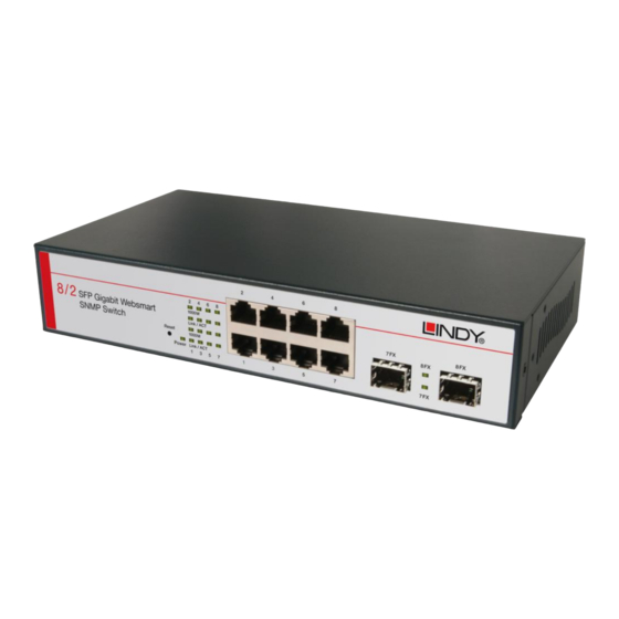
English Manual English 3 Introduction Product Overview This switch is a Web Smart Switch equipped with 8-ports 10/100/1000BaseT(X) plus 2-port gigabit SFP open slots. It was designed for easy installation and high performance in an environment where traffic is on the network and the number of users increases continuously. The compact rigid desktop size was specifically designed for small to medium workgroups. - Page 5 English Manual English 4 Security Setting MAC address filtering TCP/UDP Port filtering IGMP Snooping Backup/Recovery Configuration...
-
Page 6: Specifications
English Manual English 5 Specifications Standard IEEE 802.3 10BaseT IEEE 802.3u 100BaseTX IEEE 802.ab 1000BaseT IEEE 802.3z 1000BaseSX/LX IEEE 802.3x Flow Control IEEE 802.1x Port-based Network Access Control IEEE 802.1Q VLAN Tagging IEEE 802.3ad Port aggregation IEEE 802.1d Spanning tree protocol IEEE 802.1w Rapid Spanning tree protocol IEEE 802.1p Class of service, Priority Protocols ... -
Page 7: Package Contents
English Manual English 6 Package Contents Before you start to install this switch, please verify your package that contains the following items: One Ethernet Switch One Power Cord User Manual CD... -
Page 8: Hardware Description
English Manual English 7 Hardware Description This part primarily presents hardware of the EW-4082VM, physical dimensions and functional overview would be described. Physical Dimensions/ Weight 230 × 124 × 44 mm (L × W × H) / 0.975KG Front Panel The front Panel of the Web Smart Switch consists of 8 gigabit RJ-45 ports+... -
Page 9: Rear Panel
English Manual English 8 Table 1-1 LED Indicators Status Description Power is on. Power LED Power is off. SFP Module is connected Status LED SFP Module is disconnected Each Port upper Giga Link is connected Each Port lower 10/100/1000 Link is connected ※... -
Page 10: Software Description
English Manual English 9 Software Description This part instructs user how to set up and manage the switch through the web user interface. Please follow the description to understand the procedure. At the first, open the web browser, and go to 192.168.2.1 site then the user will see the login screen. -
Page 11: Configuration
English Manual English 10 After the user login, the right side of website shows all functions as Fig. 1-2. Figure 1-2 Configuration System System Configuration This page shows system configuration information. User can configure lots of information as below:... - Page 12 English Manual English 11 Figure 1-3 MAC Address: Displays the unique hardware address assigned by manufacturer (default). S/W Version: Displays the switch’s firmware version. H/W Version: Displays the switch’s Hardware version. DHCP Enabled: Click the box to enable DHCP ...
-
Page 13: Ports
English Manual English 12 Fallback Subnet Mask: Assign the subnet mask to the IP address Fallback Gateway: Assign the network gateway for industrial switch. The default gateway is 0.0.0.0. Management VLAN: ID of a configured VLAN (1-4094) through which you can manage the switch. - Page 14 English Manual English 13 length of the cable used to connect to other devices. Only sufficient power is used to maintain connection requirements. Mode: allow user to manually set the port speed such as Auto, 10 half, 10 Full, 100 Half, 100 Full, 1000 Full or Disabled. User may press Apply button to complete the configuration procedure.
-
Page 15: Vlan
English Manual English 14 Figure 1-4-2 VLAN A Virtual LAN (VLAN) is a logical network grouping that limits the broadcast domain, which would allow you to isolate network traffic, so only the members of the same VLAN will receive traffic from the ones of the same VLAN. Basically, creating a VLAN from a switch is logically equivalent of reconnecting a group of network devices to another Layer 2 switch. - Page 16 English Manual English 15 Figure 1-5-1 VLAN Setup The switch supports up to 16 VLANs based on 802.1Q standard. From the VLAN Membership page you can create and delete VLANs, and change the VLAN port membership. Figure 1-5-2 VLAN Per Port Configuration The 802.1Q Per Port Configuration page allows you to change the VLAN parameters for individual ports or trunks.
- Page 17 English Manual English 16 Figure 1-5-3 Port/Trunk: The port number of the port or the ID of a trunk. VLAN Aware Enabled: VLAN aware ports are able to use VLAN tagged frames to determine the destination VLAN of a frame. (Default: Enabled) ...
-
Page 18: Aggregation
English Manual English 17 VLAN 1 unless its PVID has been changed to something other than 1. Outgoing packets are tagged unless the packet’s VLAN ID is the same as the PVID. When the PVID is set to “None,” all outgoing packets are tagged. ※Note: If you select “Tagged Only”... -
Page 19: Lacp
English Manual English 18 LACP IEEE 802.3ad Link Aggregation Control Protocol (LACP) increases bandwidth by automatically aggregating several physical links together as a logical trunk and providing load balancing and fault tolerance for uplink connections. LACP Port Configuration Port: The port number. ... - Page 20 English Manual English 19 STP root device. However, if all devices have the same priority, the device with the lowest MAC address will then become the root device. Number between 0 - 61440 in increments of 4096. Therefore, there are 16 distinct values.
- Page 21 English Manual English 20 Figure 1-8-2 Figure 1-8-3 Figure 1-8-4...
-
Page 22: 802.1X
English Manual English 21 802.1X 802.1X provides port-based authentication, which involves communications between a supplicant, authenticator, and authentication server. Port refers to a single point of attachment to the LAN infrastructure. The supplicant is often software on a client device, such as a laptop; the authenticator us a network device, such as an Ethernet switch or wireless access point;... - Page 23 English Manual English 22 Figure 1-9-1 Figure 1-9-2...
- Page 24 English Manual English 23 Figure 1-9-3 802.1X Parameters Reauthentication Enabled: Sets the client to be re-authenticated after the interval specified by the Re-authentication Period. Re-authentication can be used to detect if a new device is plugged into a switch port. (Default: Disabled) ...
-
Page 25: Igmp Snooping
English Manual English 24 Figure 1-9-4 802.1x statistics for port 1 Press Statistics link, user can see the 802.1x statistics for port 1 information. Port Statistics: Statistics can be viewed on a per-port basis. Select the port that you want to view here. ... -
Page 26: Mirroring
English Manual English 25 the switch adds the host’s port number to the multicast list for that group. And, when the switch hears an IGMP Leave, it removes the host’s port from the table entry. Prevents flooding of IP multicast traffic, and limits bandwidth intensive video traffic to only the subscribers. - Page 27 English Manual English 26 Mirroring Configuration Port to Mirror to: The port that will “duplicate” or “mirror” the traffic on the source port. Only incoming packets can be mirrored. Packets will be dropped when the available egress bandwidth is less than ingress bandwidth.
-
Page 28: Qos
English Manual English 27 Figure 1-11-2 In QoS Mode, select QoS Disabled, 802.1p, or DSCP to configure the related parameters. QoS Configuration Strict: Services the egress queues in sequential order, transmitting all traffic in the higher priority queues before servicing lower priority queues. ... - Page 29 English Manual English 28 Figure 1-12-1 QoS Mode: QoS Disabled When the QoS Mode is set to QoS Disabled, the following table is displayed. Figure 1-12-2 QoS Mode: 802.1p Packets are prioritized using the 802.1p field in the VLAN tag. This field is three bits long, representing the values 0 - 7.
- Page 30 English Manual English 29 Figure 1-12-3 Figure 1-12-4 QoS Mode: DSCP DSCP: Packets are prioritized using the DSCP (Differentiated Services Code Point) value. The Differentiated Services Code Point (DSCP) is a six-bit field that is contained within an IP (TCP or UDP) header. The six bits allow the DSCP field to take any value in the range 0 - 63.
-
Page 31: Storm Control
English Manual English 30 high). The default settings map all DSCP values to the high priority egress queue. User can use the Prioritize Traffic drop-down list to quickly set the values in DSCP Configuration table to a common priority queue. Use Custom if you want to set each value individually. - Page 32 English Manual English 31 You can protect your network from broadcast storms by setting a threshold for broadcast traffic for each port. Any broadcast packets exceeding the specified threshold will then be dropped. Storm Control Configuration There are three type of traffic which can be rate limited, including broadcast multicast frame and Flooded Uncast Rate.
-
Page 33: Monitoring
English Manual English 32 Monitoring Statistic Overview Statistic Overview for all ports User can mirror traffic from any source port to a target port for real-time analysis the following figures shows clearly the statistics overview. Figure 2-1 Detailed Statics Figure 2-2... -
Page 34: Lacp Status
English Manual English 33 LACP Status LACP Aggregation Overview Figure 2-3-1 Port: The port number. Port Active: Shows if the port is a member of an active LACP group. Partner Port Number: A list of the ports attached at the remote end of this LAG link member. -
Page 35: Rstp Status
English Manual English 34 RSTP Status RSTP VLAN Bridge Overview Figure 2-4-1 Hello Time: Interval (in seconds) at which the root device transmits a configuration message. Max Age: The maximum time (in seconds) a device can wait without receiving a configuration message before attempting to reconfigure. -
Page 36: Igmp Status
English Manual English 35 RSTP Port Status Figure 2-4-2 Port/Group: The number of a port or the ID of a static trunk. Path Cost: The cost for a packet to travel from this port to the root in the current Spanning Tree configuration. -
Page 37: Veriphy
English Manual English 36 v2 Reports: Show the number of received v2 Report packets. v3 Reports: Show the number of received v2 Report packets. v3 Leave: Show the number of v3 leave packets received. Figure 2-5 VeriPHY VeriPHY Cable Diagnostics User can perform cable diagnostics for all ports or selected ports to diagnose any cable faults (short, open etc..) and feedback a distance to the fault. - Page 38 English Manual English 37 Figure 2-6-2 Figure 2-6-3 Figure 2-6-4...
-
Page 39: Ping
English Manual English 38 Ping This command sends ICMP echo request packets to another node on the network. Ping Parameters Target IP Address: IP address of the host Count: Number of packets to send. (Range: 1-20) Time Out: setting the time period of host will be Ping Use the ping command to see if another site on the network can be reached. - Page 40 English Manual English 39 Figure 2-7-1 Figure 2-7-2...
-
Page 41: Maintenance
English Manual English 40 Figure 2-7-3 Maintenance Warm Restart Press Yes button to restart the switch, the reset will be complete when the power lights stop blinking. Figure3-1 Factory Default Forces the switch to restore the original factory settings. To reset the switch, select “Reset to Factory Defaults”... -
Page 42: Configuration File Transfer
English Manual English 41 User can download firmware files for user’s switch from the Support section of your local supplier. Figure 3-3 Configuration File Transfer Configuration file transfer allows you to save the switch’s current configuration or restore a previously saved configuration back to the device. Configuration files can be saved to any location on the web management station. -
Page 43: Fcc Warning
Dieses Produkt entspricht den einschlägigen EMV Richtlinien der EU und darf nur zusammen mit abgeschirmten Kabeln verwendet werden. LINDY Herstellergarantie LINDY gewährt für dieses Produkt über die gesetzliche Regelung hinaus eine zweijährige Herstellergarantie ab Kaufdatum. Die detaillierten Bedingungen dieser Garantie finden Sie auf der LINDY Website aufgelistet bei den AGBs.
Need help?
Do you have a question about the 25028 and is the answer not in the manual?
Questions and answers