
Related Manuals for Lindy 25051


Summary of Contents for Lindy 25051
-
Page 1: Port Switch
8-Port Switch with Auto MDI/MDI-X 8 Port 10/100 Base-TX Switch User Guide Rev. AUG, 2002... - Page 2 Introduction Wellcome to the World of Mini-Networking. In the modern business society, communication and sharing information is crucial. Computer networks have proven to be one of the fastest modes of communication. The 8-Port Switch are compact and attractively designed for desktop use.
- Page 3 Package Contents ??8-Port Switch ??One DC power adapter ??User’s Guide 8TP Auto MDI/MDI-X Switch Rubber Feet DC power Adapter User’s Guide Figure 1-2. Package Contents Compare the contents of your 8-Port Switch with the standard checklist above. If any item is missing or damaged, please contact your local dealer for service.
-
Page 4: Hardware Description
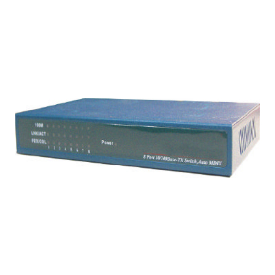
Hardware Description This section mainly describes the hardware of the 8-Port Switch. The physical dimensions of the 5-Port Switch and 8-Port Switch are the same : 164mm(W) X 100mm(D) x 26mm(H) Front Panel The LED indicators are located on the frond panel of the Switch. They provide a real-time indication of systematic operation status. -
Page 5: Rear Panel
The following table provides descriptions of the LED statuses and their meaning. Status Color Description Power Green The power of the Switch is On Green The port is connecting with 100Mbps. 100Mbps The connection between the Switch and the device is 10Mbps, if the LINK/ ACT light is on. -
Page 6: Network Application
??Auto MDI/MDI-X: It can detect the cable straight connect NIC or cascade to a hub or switch without change the connector, the maximum distance between the Switch to another device is 100 meters. ??DC Power Connector: Plug DC Power Adapter’s female end into this device, and the male end of the DC Power Adapter into a power outlet. - Page 7 Figure 3-1. Stand Alone Application Enlarge Your Network You can use Uplink port of the 8-Port Switch to connect with another hub or switch to interconnect each of your small switched workgroup to form a large switched network. You can connect anyone switch port to hub or switch without crossover cable by the Auto MDI/MDI-X function.
- Page 8 Figure 3-2. Example of enlarging your network...
-
Page 9: Troubleshooting
Trouble Shooting The Switch can be easily monitored through panel indicators to assist in identifying problems. This section describes common problems you may encounter and where you can find possible solutions. ??Diagnosing LED Indicators IF Link indicator does not light up after making a connection. You may check whether network interface (e.g., a network adapter card on the attached device), network cable, or switch port is defective or not. -
Page 10: Technical Specification
Technical Specification This section provides the specifications of the 5-Port Switch/ 8-Port Switch : Specification Standards Compliance IEEE 802.3 10BASE-T Ethernet, IEEE 802.3u 100BASE-TX Fast Ethernet ANSI/IEEE standard 802.3 N-Way auto-negotiation Protocol CSMA/CD Max Forwarding Rate and 14,880 pps Ethernet port, Max Filtering Rate 148,800 pps per Fast Ethernet port LED Indicators... - Page 11 Federal Communications commission (FCC) Statement This Equipment has been tested and found to comply with the limits for a Class B digital device, pursuant to Part 15 of FCC rules. These limits are designed to pro reasonable protection against harmful interference in a residential installation.
Need help?
Do you have a question about the 25051 and is the answer not in the manual?
Questions and answers