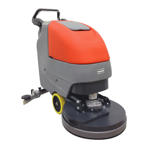
PowerBoss Phoenix 20 User Manual
Walk-behind scrubber
Hide thumbs
Also See for Phoenix 20:
- User manual (40 pages) ,
- User manual (40 pages) ,
- Manual (41 pages)
Table of Contents

Subscribe to Our Youtube Channel
Related Manuals for PowerBoss Phoenix 20


Summary of Contents for PowerBoss Phoenix 20
-
Page 1: User Manual
User Manual Phoenix 20 Walk-Behind Scrubber Traction Drive Cylindrical Deck... - Page 2 This manual is furnished with each new Phoenix 20. This provides the necessary operating and preventive maintenance instructions. Operators must read and understand this manual before operating or servicing this machine. This machine was designed to give you excellent performance and efficiency. For best results and minimal cost, please follow the general guidelines below: ·...
-
Page 3: Technical Specifications
Technical Specifications Model Phoenix 20 Traction Drive Cylindrical Model No. PHX20CQP / PHX20CQPG / 3336074QP 40 amps Current (Max) 140Ah @20 hr Battery Capacity (Lead Acid) 100Ah @20 hr Battery Capacity (Gel) 69 dBA Sound Level 20 in (51 cm) -
Page 5: Table Of Contents
Brush Loading / Unloading ................27 Bail Handle ..................11 Brush Deck Maintenance ................27 Handle Adjustment Knobs ..............11 The Phoenix 20 Cylindrical ............... 28 Key Switch ..................11 Machine Operation ..................30 Direction Switch .................. 11 To Turn ON Machine: .................. 30 Squeegee Lift Lever ................ -
Page 6: Safety Instructions
Safety Instructions IMPORTANT SAFETY INSTRUCTIONS Operators must read and understand this manual before operating or maintaining this machine. Do not operate this machine in flammable or explosive areas. This machine is designed solely for scrubbing dirt and dust in an indoor environment. Minuteman does not recommend using this machine in any other capacity. -
Page 7: Unpacking Instructions
Unpacking Instructions Inspection Carefully unpack and inspect your Phoenix 20 Walk-Behind Scrubber for shipping damage. Follow unpacking instructions on shipping pallet. Each unit has been tested and thoroughly inspected before shipment. Any damage is the responsibility of the delivery carrier who should be notified immediately. -
Page 8: Machine Overview
Machine Overview Machine Overview - Front CUP HOLDER SOLUTION FILL PORT RECOVERY TANK LID RECOVERY TANK BRUSH DECK FRONT WHEEL (see note) REAR CASTER SOLUTION TANK * NOTE - Front tires are foam filled to be maintenance-free. No air can be added. - Page 9 Machine Overview Machine Overview - Rear BAIL HANDLE CONTROL PANEL SQUEEGEE LIFT LEVER SOLUTION TANK DRAIN HOSE / LEVEL INDICATOR RECOVERY TANK DRAIN HOSE BRUSH LIFT PEDAL ONBOARD CHARGER CORD REAR SQUEEGEE CIRCUIT BREAKERS DIAGNOSTIC CODE GUIDE RECOVERY HOSE SOLUTION CONTROL LEVER...
-
Page 10: Controls
Machine Overview Controls BAIL HANDLE HANDLE ADJUSTMENT KNOB KEY SWITCH DIRECTION SWITCH SQUEEGEE LIFT LEVER BATTERY / FAULT GAUGE SPEED CONTROL CHARGE STATUS INDICATOR SOLUTION CONTROL LEVER... -
Page 11: Bail Handle
Machine Overview Bail Handle (A) When the scrub deck is lowered to the floor, the bail handle enables the brush motor and moves the machine forward once depressed. Handle Adjustment Knobs (B) Allows the handle position to be raised or lowered. Key Switch (C) Controls the machine’s power (Off/On) with a key for safety. -
Page 12: Optional Hour Meter
Machine Overview Optional Hour Meter Powerboss offers an optional hour meter for the Phoenix 20. The optional kit replaces the power cord mounting bracket at the rear of the machine with one that contains an hour meter, which records the brush motor operating time. -
Page 13: Circuit Breakers
Machine Overview Circuit Breakers The circuit breakers are located at the bottom of the back panel of the machine. Main Control Circuit Breaker - 4A Brush Motor Circuit Breaker - 30A Vacuum Motor Circuit Breaker - 20A Drive Motor Circuit Breaker - 20A If any of the functions above are not operating, check if the circuit breaker buttons have tripped. -
Page 14: Battery Compartment
Machine Overview Battery Compartment The battery compartment is located under the recovery tank. The Battery compartment can be accessed for servicing and mainte- nance by tilting the recovery tank (make sure recovery tank has been drained before tilting). The battery compartment contains two 12-volt batteries connected in series. -
Page 15: Diagnostic Code Guide
Machine Overview Diagnostic Code Guide When an error or fault occurs within the machine, a fault code will appear on the battery gauge represented by a specified number of flashing LEDs. (See “Troubleshooting” for further information) -
Page 16: Handle Adjustment
Machine Overview Handle Adjustment The Phoenix 20 handle was designed with operator comfort in mind. The angle and horizontal position of the handle can be adjusted to suit the needs of the operator. Angle Adjustment The handle angle can be adjusted without tools by loosening the Angle Adjustment Knob (A) on each side and rotating the handle to the desired position. -
Page 17: Horizontal Adjustment
Machine Overview Horizontal Adjustment The horizontal position can be adjusted by removing the 4 Mounting Bolts (B) (2 each side) with a 9/16” socket and sliding the Mounting Plate (P) to one of the 3 available positions. The machine is shipped from the factory in position 1. -
Page 18: Solution Tank Drain Hose
Machine Overview Solution Tank Drain Hose The solution tank may be drained by removing the Solution Tank Drain Hose (A) from the Hose Barb (B) and routing the hose to a floor drain. Solution Level Indicator The Solution Tank Drain Hose also serves as a water level indicator for the solution tank. -
Page 19: Solution Fill Filter
Machine Overview Solution Fill Filter The Solution Fill Filter (B) should be cleaned regularly. To remove, simply open the Solution Tank Lid (A) and pull the filter out. Recovery Tank Drain Hose Twist Cap to Open and Drain Twist & Lift cap to clean out large debris... -
Page 20: Screened Float
Machine Overview Screened Float If the recovery tank (C) is overfilled or a large amount of foaming is present, the screened float (B) blocks the vacuum intake inside the tank protecting the vacuum motor and internal electronics from water damage. It is essential to keep the float in working order through regular maintenance. -
Page 21: Screened Float Removal
Machine Overview Screened Float Removal The screened float is positioned between the vacuum manifold (A) and recovery tank (C). The screened float (B) can be accessed by removing the 1.5” bolt (D) and two 1.25” bolts (E) that attach the manifold to the recovery tank using a 7/16”... -
Page 22: In-Line Solution Filter Assembly
Machine Overview In-Line Solution Filter Assembly The pump and solution solenoid, which shuts off solution flow when the bail handle is released, are protected from debris by the in-line filter assembly. The filter assembly is located at the front of the machine above the brush deck. It is important to check and clean the screened washer inside the assembly regularly to ensure proper solution flow. -
Page 23: Rear Squeegee
Machine Overview Rear Squeegee Cleaning the Squeegee Changing the Squeegee Blades Check the squeegee (A) daily and clean as Check the inner and outer squeegee blades on A Squeegee necessary. the squeegee (A) weekly for signs of wear. The B Star-shaped knob 1. -
Page 24: Squeegee Blades
Machine Overview Squeegee Blades Angle Adjustment The angle adjustment is the decisive factor in ensuring that the squeegee blades on the squeegee lie evenly on the floor. 1. Park the machine on a level surface and lower the squeegee. 2. Loosen the lower wing nut (B) on the adjust- ing screw (C) and adjust the squeegee using the adjusting screw so that the ends of the squeegee blades still have contact with the... -
Page 25: Squeegee Blades
Machine Overview Squeegee Blades Height Adjustment If streaks are present, despite an optimum angle adjustment, the clearance between the caster wheels and floor must be adjusted by 3 mm changing the number of washers underneath the bracket that holds the wheel. The squeegee height is preset at the factory to 3mm. -
Page 26: Brush Deck Maintenance
Machine Overview Brush Deck Maintenance Sprayjet Maintenance The sprayjets deliver solution to the floor. The spray tip should be cleaned weekly to ensure good cleaning results. To Install To Remove Figure 1 Figure 2 Figure 3 Spray tip removal and installation for cleaning 1. -
Page 27: Brush Loading / Unloading
Machine Overview Brush Deck Maintenance Debris Tray Maintenance The Debris Tray (A) collects debris from the floor during operation. It must be cleaned regularly. Remove the tray from the deck by tilting the bottom up, then sliding it out to the side. -
Page 28: The Phoenix 20 Cylindrical
The Phoenix 20 Cylindrical This machine was designed with total operator comfort and ease of use in mind. All machine components have been designed as a total system to efficiently clean dirty floors. Please contact your PowerBoss representative for specific recommendations for the correct brush type and chemical applications. - Page 29 The Phoenix 20 Cylindrical WARNING! - Be sure you understand the machine controls and their functions. - While on ramps or inclines, avoid sudden stops when tanks are filled. - Avoid abrupt sharp turns. Slow down driving speed when going downhill.
-
Page 30: Machine Operation
Machine Operation Machine Operation To Turn ON Machine: Turn key to operate position ( I ). Wait for battery gauge to stop flashing. (If flashing continues, see troubleshooting guide) To Turn ON Vacuum: Lower squeegee into operating position, vacuum motor will turn ON automatically. To Turn ON Brush Motor: Lower the scrub deck to the floor by moving the brush lift pedal from the “home”... -
Page 31: To Charge Batteries
Machine Operation To Charge Batteries: When the battery / fault gauge reaches the red zone the batteries need to be recharged. Take the machine to a well ventilated area, unwind the battery charger power cord from the electrical box cover and plug into an appropriate power source. After approximately 10 seconds the battery charge status indicator will turn on. -
Page 32: After Use
After Use 1. When finished scrubbing, lift the scrub deck. Lift the rear squeegee (the vacuum motor will turn off after 10 seconds). Move the machine to a service area for daily maintenance and review items that may need service. 2. -
Page 33: Maintenance
Maintenance D a i ly W e ek l y M o n th l y Y e a rl y C h a rg e B a tt e r ie s I ns p ec t B ru sh L u b r ica tio n –... - Page 34 Troubleshooting Prob lem Possi ble Cau se Rem edy Worn or torn squeegee blades Rot ate or rep lace blades Recovery t ank full Em pty recovery tank Recovery t ank drain hose leak Secure drain hose cap or replace Recovery t ank lid gasket leak Replace gasket lid cover properly Po or water p ic k-up...
- Page 35 Troubleshooting Problem Possible Cause Remedy Tripped Control Power circuit breaker Reset circuit breaker Batteries have low charge Recharge batteries Battery charger operating Unplug battery charger when charge is complete Machine does not operate Key switch off Turn key on Bail handle depressed too quickly after Turn key off, turn on, wait until battery gauge turning key on lights up without flashing...
-
Page 36: Troubleshooting
Troubleshooting Fault / Diagnostic Codes The Battery / Fault gauge will flash when a fault is detected. A decal labeled “Diagnostic Codes” is located below the battery gauge as an abbreviated and convenient guide to determine the cause of the fault and the remedy (refer to machine or see “Diagnostic Code Guide” section of this manual). The flashing codes are for the following: The battery needs charging, there is a bad The motor has a short circuit to a battery... - Page 37 Troubleshooting Not used. A controller fault is indicated. Make sure that all connections are secure. The controller is being inhibited from driving, Not used. this may be because the battery charger is connected. The bail handle was activated prior to turning An excessive voltage has been applied to the the machine on.
-
Page 38: Warranty
PowerBoss Incorporated Made Simple Commercial Limited Warranty Revision F Effictive November 1, 2008 Powerboss made Simple Industrial Limited Warranty Minuteman International owner of PowerBoss warrants to the original purchaser/user that the product is free from defects in workmanship and materials under normal use. PowerBoss will, at its option, repair or replace without charge, parts that fail under normal use and service when operated and maintained in accordance with the applicable operation and instruction manuals. - Page 39 Travel* Labor Parts E ngine E xtended Warranty Costs Walk behinds Battery sweepers Ninety days One year One year 2 years P arts + Labor (or 2000 Hours) IC sweepers Ninety days One year One year Through m anufacturer 2 years P arts + Labor (or 2000 Hours) Battery scrubbers Ninety days Two years...
- Page 40 PowerBoss Incorporated · 175 Anderson Street P.O. Box 1227 · Aberdeen, North Carolina 28315 Phone: 1-800-982-7141 · Fax: 1-800-277-7141 · Local: 1-910-944-7409 www.powerboss.com A Member of the Hako Group 988728UMPB Rev B 04/10...
Need help?
Do you have a question about the Phoenix 20 and is the answer not in the manual?
Questions and answers