Table of Contents
Advertisement
Quick Links
Advertisement
Table of Contents

Related Manuals for PowerBoss Phoenix 35


Summary of Contents for PowerBoss Phoenix 35
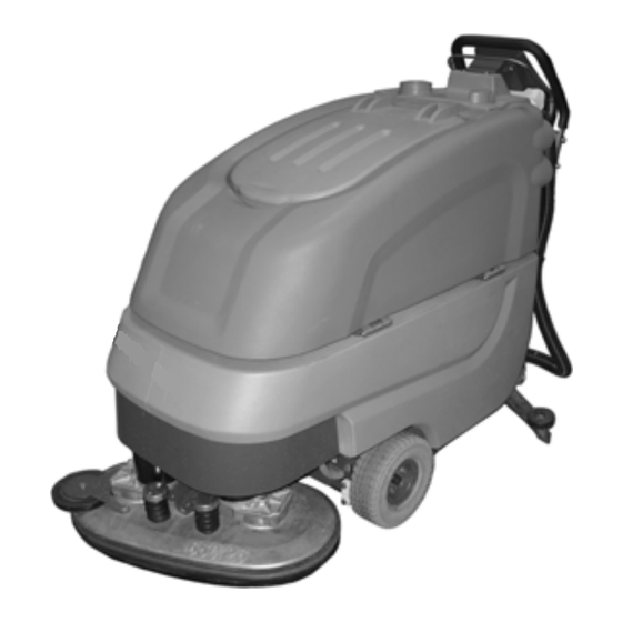
- Page 1 User Manual Phoenix 35...
- Page 2 The outstanding operational characteri- be read in conjunction with each other, stics of the Phoenix 35 should justify the as well as with Phoenix 35 labels, in- confidence you demonstrated in ma- struction plates, and applicable govern- king this purchase.
- Page 3 The reader should notify Aberdeen, NC 28315 compensatory, directly or indirectly re- PowerBoss if any errors in this instruc- U.S.A. sulting from the publication, use of, ap- tion manual are suspected. PowerBoss plication, or reliance on this document...
- Page 4 Proper Use The Phoenix 35 is a vacuum scrubbing machine. Its intended scope of applica- tion is for wet cleaning of level, smooth, hard-surfaced floors in accordance with the provisions of this instruction manu- al, applicable governmental regulati- ons, manufacturer specifications, and machine labels (collectively, "proper...
-
Page 5: Notes On Warranty
Any da- however, that failure to maintain and mage is the responsibility of the delivery service your Phoenix 35 in accordance carrier who should be notified immedia- with its proper use may void the warran- tely. -
Page 6: Table Of Contents
Cylindrical Brush Deck ..40 Instruction....15 PowerBoss System Mainte- 5.8.1 Clean Dirt Hopper ..40 Initial Charging Procedure . -
Page 8: Safety Information
SAFETY Safety Information Safety and Warning Symbols All paragraphs in this manual referring to your personal safety, the safety of your machine and the environment pro- tection are attributed one of the follo- wing warning symbols: Safety Symbols Description WARNING Indicates a hazardous situation which could result in death or serious injury. -
Page 9: General Provisions
Phoenix 35 unit in their entirety befo- plates be replaced. re operation. These materials con- • The Phoenix 35 is designed for in- tain valuable information regarding door use only. Store machine in- the safe operation of the machine. -
Page 10: Operational Precautions
SAFETY Operational Precautions cative of malfunctions, etc. Any signs operator's control. The Phoenix 35 is a battery-opera- of potential problems must be reme- The Phoenix 35 is not desi- ted hard surface floor cleaning sy- died before actual operation com-... -
Page 11: Maintenance Precautions
SAFETY Maintenance Precautions • Before commencing operation of the • Maintenance and repairs must be machine, check for obvious signs of performed by qualified personnel on- loose parts, potential conditions indi- ly. Maintain adjustments on machine cative of malfunctions, etc. Any signs pursuant to specifications noted in of potential problems must be reme- the service manual. -
Page 12: Battery And Electrical System Precautions
• Observe all operating, use, and safe- Precautions standards and government regulati- ty instructions provided by the appro- The Phoenix 35 utilizes lead ons, if any. priate battery manufacturer. acid batteries. Lead acid batte- • The electrical system of the machine... -
Page 13: Cleaning Solution Use And Disposal Precautions
(low stems or basins! foaming) should be used in the Phoenix 35. Cleaning agents / deter- gents should be mixed with water in ratios established by product labels and or manufacturer recommendati- ons. -
Page 14: Labels At The Machine
B = Maximum inclination of 2% ne. Replace missing or illegible labels immediately. C = Do not clean the machine by means of high-pressure cleaning equipment Powerboss nameplate (Abb. 1/1) Machine identification number (Abb. 1/ Recovery tank drain hose (Abb. 1/3) Abb.1... - Page 15 SAFETY...
-
Page 16: First Operation
FIRST OPERATION First Operation maintenance chapter. Start Machine 3. Install batteries and connect battery Proceed with the following to set the Instruction plug, see maintenance chapter. machine to operating mode: Only persons trained by qualified Minu- 4. Check battery charge and recharge •... -
Page 17: Operation
FIRST OPERATION Operation After Work Transporting the Machine 1. Switch on the machine. 1. Move machine to a suitable site for To transport the machine to the work ar- 2. Use lever (Fig5/4) to lower squee- maintenance. ea, switch it on, lift-out squeegee and gee. -
Page 18: Operation
OPERATION Operation Method of Operation General The Phoenix 35 is a vacuum scrubbing machine for wet cleaning of hard-sur- faced floors. 3.1.1 Brush Deck Lower brush deck (Abb. 3/1) via pedal before scrubbing. The brushes rotate and solution supply switches on auto- matically. -
Page 19: Squeegee
OPERATION 3.1.3 Squeegee 3.1.5 Traction Drive Accessories such as brushes, The movable squeegee (Abb. 3/3) con- The machine features a continuous rollers, pads, pad holder with sists of the squeegee lift mechanism, traction drive (Abb. 3/6). The electronic centerlock and sealing strips the vacuum motor and squeegee bla- traction drive control realises modificati- are available. -
Page 20: Operating And Indicating Ele- Ments
OPERATION Operating and Indicating Ele- ments 3.2.1 Operating Panel 1 Display 2 Key switch 3 Battery charge indication 4 LDS indicator 5 Symbol brush drive 6 Symbol vacuum drive 7 Hourmeter 8 Symbol Service indicator 9 free 10 Symbol Silence Kit (optional) 11 Symbol solution flow 12 Tip-switch Silence Kit (optional) 13 Tip-switch solution dosage... - Page 21 OPERATION Display (Abb. 4/1) This panel allows centralized monito- 1.1.1.1 ring of functions and detection of all LDS indicator (Abb. 4/4) Hourmeter (Abb. 4/7) available operating modes. Upon switching on, the LDS indication Upon switching on, the hourmeter is output on the panel to show the cur- briefly displays the software version rent battery charge condition during and the last error code.
- Page 22 This symbol appears when Silence Kit Hand cleaning tool (optional) tip-switch is switched on. Hand-cleaning tool with spray function for the Phoenix 35 with scrubbing tool Solution supply ON/OFF tip-switch connection for thorough cleaning on (Abb. 4/14) areas which are difficult to reach.
-
Page 23: At The Machine
OPERATION 3.2.2 At the Machine 1 Brush deck pedal 2 Opening of solution tank 3 Squeegee lever 4 Solution filter 5 Recovery drain hose 6 Solution level indication 7 Brush ejector 8 Power connection charger unit Abb.5... - Page 24 OPERATION Brush deck pedal(Abb. 5/1) Power connection charger unit Use this pedal to lift and lower the brush (Abb. 5/8) deck. The power connection supplies the charger unit with power. Opening of solution tank (Abb. 5/2) The solution tank is filled after folding up the opening.
- Page 25 OPERATION Dirt hopper guiding rail (Abb. 6/1) The dirt hopper located at the cylindrical brush deck is fastened by a guiding rail. This dirt hopper may be easily removed for cleaning. Lever for cylindrical brush seating (Abb. 6/2) This lever (both sides) is used to re- lease/lock the cylindrical brush seating.
-
Page 26: Maintenance And Care
MAINTENANCE Maintenance and Care Minuteman System Mainte- System Maintenance I : nance (every 125 hours of operation) General The Minuteman System Maintenance: To be performed by qualified personnel Before proceeding to mainte- • guarantees reliable operability of the of authorized Minuteman Service Cent- nance and care work you are Minuteman machines (preventive re in accordance with the machine-spe-... -
Page 27: Maintenance Document
MAINTENANCE Maintenance Document Handing over System Maintenance I System Maintenance II System Maintenance I 125 operating hours 250 operating hours 375 operating hours Upgrade Workshop stamp Workshop stamp Workshop stamp Test drive Handing over to the customer Instruction carried out on: carried out on: carried out on: carried out on:... -
Page 28: Maintenance Schedule
MAINTENANCE Maintenance Schedule System Maintenance Customer The daily and weekly maintenance in- tervals must be performed by the custo- mer/operator. Interval To be performed daily weekly Fill solution tank and proceed to chemical agent dosage Charge batteries Check brush head and clean if required Check squeegee and clean if required Clean tank lid seal of the recovery tank Empty recovery tank. - Page 29 MAINTENANCE System Maintenance I The following maintenance work must be performed by an authorized Minute- man Service workshop. Interval To be performed every 125 hours of operation Check battery charger Check tank lid seal of the recovery tank and replace if required Check drain hose of the recovery tank and replace if required Grease joints at the brush lift-out Check wheel fixing screws and tighten (24 lb ft) if required...
- Page 30 MAINTENANCE System Maintenance II The following maintenance work must be performed by an authorized Minute- man Service workshop. Interval To be performed every 250 hours of operation Perform maintenance works according to System Maintenance I Inspect steering rollers for tread damages and bearing slackness and replace if required Check drain hose of the recovery tank and replace if required Check deflector roller of the brush head and replace if required...
- Page 31 MAINTENANCE System Maintenance S (Safety check) The following maintenance work must be performed by an authorized Minute- man Service workshop at least once a year. Interval To be performed every 500 hours of operation Perform maintenance works according to System Maintenance II Clean travel drive motor from carbon dust and check carbon brushes for smooth operation and wearing and replace carbon brushes if required Clean brush motors from carbon dust and check carbon brushes for smooth opera-...
-
Page 32: Battery Systems
MAINTENANCE Battery Systems 1 LDS display 2 Charger indicator 3 Charger 4 Mains cable charger 5 Battery connector 6 Batteries 7 Recovery tank 8 Support 9 Wiring diagram Handling and changing the batteries may be performed only by maintenance staff. Abb.7... -
Page 33: Charge Batteries
(Abb. 7/9). Provide for 4.4.3 Maintenance of Drive Batte- Powerboss contract workshops. tight fitting and grease poles. ries Refer to operating instructions 88-60- 4.4.6 Disposal of Batteries... -
Page 34: Solution Tank
MAINTENANCE Solution Tank 1 Solution tank 2 Marker 3 Fill level hose 4 Solution filter 5 Tank lid Abb.8... -
Page 35: Fill Solution Tank
MAINTENANCE 4.5.1 Fill Solution Tank 4.5.3 Solution Filter Fill solution tank (Abb. 8/1) before work Check solution filter (Abb. 8/4) at week- or as required. Park vehicle on level ly intervals and clean or replace if requi- ground. Open tank lid (Abb. 8/5) and fill red. -
Page 36: Recovery Tank
MAINTENANCE Recovery Tank 1 Recovery tank 2 Drain hose 3 Suction filter 4 Tank lid Abb.9... -
Page 37: Empty Recovery Tank
MAINTENANCE 4.6.1 Empty Recovery Tank 4.6.2 Clean Recovery Tank Clean recovery tank (Abb. 9/1) at daily Clean recovery tank (Abb. 9/1) at daily intervals, as required or upon acoustic intervals or as required. signal (increased suction turbine 1. Empty recovery tank, siehe Ab- speed). -
Page 38: Disc Brush Deck
MAINTENANCE Disc Brush Deck 4.7.1 Clean Brushes 4.7.2 Change Brushes Clean brushes of the brush deck (Abb. Check brushes of the brush deck for 1 Brush deck pedal 10/2) at daily intervals or as required. wearing at weekly intervals. Replace 2 Brush deck 1. -
Page 39: Cylindrical Brush Deck
MAINTENANCE Cylindrical Brush Deck 4.8.1 Clean Dirt Hopper 4.8.2 Remove Brushes 1 Brush deck pedalt Clean dirt hopper (Abb. 11/2) at daily in- 1. Lift up cylindrical brush deck (Abb. 2 Dirt hopper tervals or as required. 11/3) by pedal (Abb. 11/1). 3 Cylindrical brush deck Remove dirt hopper from the right ma- 2. -
Page 40: Squeegee
MAINTENANCE Squeegee 4.9.1 Cleaning the Squeegee 4.9.2 Changing Squeegee Blades Check the squeegee (Abb. 12/1) daily Check the inner and outer squeegee 1 Squeegee and clean as necessary. blades on the squeegee (Abb. 12/1) 2 Star-shaped knob To clean it lift up the squeegee, pull off weekly for signs of wear. -
Page 41: Adjusting The Blades
MAINTENANCE 4.9.3 Adjusting the Blades Angle Adjustment The angle adjustment is the decisive factor in ensuring that the squeegee blades on the squeegee lie evenly on the floor. 1. Park the machine on a level surface and lower the squeegee. 2. - Page 42 MAINTENANCE Height Adjustment The height adjustment is set to 3 mm at the factory. If streaks are produced, de- spite an optimum angle adjustment, the clearance between the casters and floor must be adjusted by changing the number of washers on the holder. 3 mm In cases of very smooth floors, e.g.
- Page 43 MAINTENANCE...
- Page 44 TECHNICAL Technical Data Disc brush deck Cylindrical brush deck 68.0 65.0 Machine length Machine height 43.7 43.7 Machine width without Squeegee 34.7 Machine width with Squeegee 43.3 43.3 Working width 33.5 27.6 Squeegee width 43.3 43.3 Surface performance theoretical 36600 ft²/h 3400 m²/h...
- Page 45 TECHNICAL Noise emission The sound pressure level measured under maximum conditions of use (LwA) according to DIN EN 60335-2-72 amounts to: dB (A) The sound pressure level measured (at the ear of the driver) under normal condi- tions of use (LpA) according to DIN EN 60335-2-72 amounts to: dB (A) Measurement inaccuracy (KpA): dB (A)
- Page 46 All warranty claims must be submitted through and approved by factory authorized repair stations. This warranty does not apply to normal wear, or to items whose life is dependent on their use and care. Parts not manufactured by PowerBoss are covered by and subject to the warranties and/or guarantees of their manufacturers.
- Page 47 PowerBoss International Made Simple Commercial Limited Warranty Travel* Labor Parts Engine Extended Warranty Costs Walk behinds Battery sw eepers Ninety days One year One year 2 years Parts + Labor (or 2000 Hours) IC sw eepers Ninety days One year...
- Page 48 PowerBoss Incorporated · 175 Anderson Street P.O. Box 1227 · Aberdeen, North Carolina 28315 Phone: 1-800-982-7141 · Fax: 1-800-277-7141 · Local: 1-910-944-7409 www.powerboss.com A Member of the Hako Group 988033UMPB Rev * 08/09...
Need help?
Do you have a question about the Phoenix 35 and is the answer not in the manual?
Questions and answers