
Related Manuals for PowerBoss Phoenix 26


Summary of Contents for PowerBoss Phoenix 26
-
Page 1: User Manual
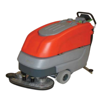
® PowerBoss The Power of Clean User Manual Operation & Safety Phoenix 26 PowerBoss,Inc. A member Of The Hako Group... - Page 2 Your authorized PowerBoss dealer will be pleased The Phoenix 26 may be used by Qualifi ed persons to answer further questions regarding the unit or the familiar with the machine and aware of possible operation and maintenance manual.
- Page 3 For refund of such damage, have the freight The maintenance work has to be performed by an authorized forwarder confi rm damage and mail notifi cation PowerBoss service center and confi rmed in the “Maintenance along with waybill to: Certifi cate” which is the warranty document.
-
Page 4: Table Of Contents
1.2 General Provisions ................6 PowerBoss System Maintenance II ..........26 1.3 Provisions for Operation ..............6 PowerBoss System Maintenance S (Safety check) ....... 27 1.4 Maintenance instructions ..............7 5.4 Battery Systems ................28 1.5 Specifi c Hazards ................7 5.4.1 Charging The Batteries ............ -
Page 5: Safety Information
Safety Information 1 Safety information 1.1 Safety and Warning Symbols All paragraphs in this manual referring to your personal safety, the safety of your machine and the environment protection are recognized by one of the following warning symbols: Symbol Hazardous for ... Description Indicates a hazardous situation which could result in death or Warning... -
Page 6: General Provisions
Lift the brush head before going over • Only persons trained by qualifi ed charging procedure and comply with obstacles (doorsteps). PowerBoss personnel are authorized the operating instructions of the • Empty dirty water tank before folding to operate, service and repair the charger as well as with those of the recovery tank over. -
Page 7: Maintenance Instructions
• Follow the operating instructions of beyond this please contact your local means of high-pressure cleaning the battery manufacturer. PowerBoss service center. equipment. • Handling and changing of the • Observe the maintenance activities • The use of aggressive detergents is... -
Page 8: Information For Protection Of Environment
Safety Information 1.6 Information for Protection of Environment • For safe use of substances inheriting a danger to health and environment specifi c knowledge is required. • Observe the legal directives and local regulations for disposal of detergents, see Water Management Act. •... -
Page 9: Labels On The Machine
C = Do not clean the machine by means of high-pressure cleaning equipment (Fig. 1/2) PowerBoss nameplate (Fig. 1/1) Machine identifi cation number (Fig. 1/2) Dirty water drain hose (Fig. 1/3) Infl ation Pressure (Fig. 1/4) = 65 psi... -
Page 10: First Operation
PowerBoss dealer. Your 2. Install brushes and squeegee, see occur. Use the following PowerBoss dealer will be maintenance chapter. procedure reset the machine into informed upon delivery of the unit 3. Install batteries and connect battery... -
Page 11: Operation
First Operation 2.5 Operation 2.8 Transport Mode 2.7 After Work 1. Turn on the machine via ignition When transporting unit to; switch unit on, lift 1. Park machine on a suitable site for switch. squeegee and scrub head and actuate the maintenance. -
Page 12: Operation
Operation 3 Operation 3.1 Method Of Operation General The Phoenix 26 is a vacuum scrubbing machine for wet cleaning of hard surfaced fl oors. 3.1.1 Scrub Head Assembly Lower the scrub head assembly (Fig. 3/1) via pedal before scrubbing. The brushes will rotate and the water supply turns on automatically. -
Page 13: Squeegee
(Fig. 3/4) by a vacuum motor blades are available. Contact your PowerBoss and suction hose. For cleaning and Dealer for more information collecting water in places where access is diffi... -
Page 14: Control Panel & Operation Indicators
Operation 3.2 Control Panel & Operation Indicators 3.2.1 Operating Panel 1 Display 2 Key Switch 3 Battery Charge Indicator 4 LDS Indicator 5 Symbol for Brush Drive 6 Symbol for Vacuum Motor 7 Hour Meter 8 Symbol for Service Indicator 9 free 10 Symbol for Silence Kit (optional) 11 Symbol for Clean Water metering... - Page 15 Operation Display (Fig. 4/1) This panel allows centralized monitoring 1. 1. 1. 1. of functions and status of all available operating modes. Hour Meter (Fig. 4/7) When switched on, the hour meter LSD Indicator (Fig. 4/4) briefl y displays the software version and Upon switching on, the LDS indicator is The ignition key switch turns the electrical the last error code.
- Page 16 Hand Cleaning Tool (optional) Hand-cleaning tool with spray function for the Phoenix 26 with scrubbing tool connection for thorough cleaning on areas Clean Water Supply ON/OFF Switch Clean Water Metering Symbol (Fig. 4/11) which are diffi...
-
Page 17: At The Machine
Operation 3.2.2 At The Machine Forward / Reverse lever Opening For Clean Water Tank Lever For Squeegee Lift / Lower Clean Water Filter Dirty Water Drain Hose Clean Water Level Indicator Brush Ejector Power Cord For Charger Pedal For Scrub Head 10 Pedal For Scrub Head Pressure Fig.5... - Page 18 Operation Forward/Reverse Lever (Fig. 5/3) With the machine being switched on, Recovery Tank Drain Hose (Fig. 5/5) the forward/reverse lever allows continuous This hose allows draining of the dirty water regulation of speed. If pulled to maximum collected in the dirty water recovery tank. position, maximum speed is attained.
- Page 19 Operation Debris Hopper Guide Rail (Fig. 6/1) The debris hopper located at the cylindrical broom head is fastened by a guide rail. This debris hopper may be easily removed for cleaning. Lock Lever For Cylindrical Brush (Fig. 6/2) The cylindrical Scrub brush may be easily removed without tools.
-
Page 20: Technical Data
Technical Data 4 Technical Data Unit Of Measure Disc Brush Head Cyl.Brush Head Machine length cm / in 151 / 59.44 159 / 62.59 Machine height cm / in 111 / 43.70 111 /43.70 Machine width without Squeegee cm / in 68 / 26.77 68 / 26.77 Machine width with Squeegee... - Page 21 Technical Data Noise Emission Metric unit Standard Soundproofi ng Soundproofi ng package Silence Kit The sound pressure level measured under maximum conditions of use (LwA) according to DIN EN 60335-2-72 dB (A) amounts to: The sound pressure level measured (at the ear of the driver) under normal conditions of use (LpA) according to dB (A) DIN EN 60335-2-72 amounts to:...
-
Page 22: Maintenance And Care
Safety PowerBoss System Maintenance S: The PowerBoss System of Maintenance is Information chapter! (every 500 hours of operation safety check) structured in separate modules and To be performed by an qualifi ed personnel determines specifi... -
Page 23: Maintenance Document
Maintenance and Care 5.2 Maintenance Document Handing over PowerBoss-System PowerBoss System PowerBoss System Upgrade Maintenance I Maintenance II Maintenance I Test drive Handing over to the customer 125 operating hours 375 operating hours 250 operating hours Instruction Workshop stamp Workshop stamp... -
Page 24: Maintenance Schedule
Maintenance and Care 5.3 Maintenance Schedule PowerBoss System Maintenance Customer The daily and weekly maintenance intervals are to be performed by the customer / operator. To Be Performed Interval Daily Weekly Fill clean water solution tank. Add chemical agent Charge batteries... -
Page 25: Powerboss System Maintenance I
Maintenance and Care PowerBoss System Maintenance I The following maintenance works are to be performed by an authorized PowerBoss Service workshop. To be performed Interval Every 125 hours of operation Check battery charger Check seal of recovery tank lid. Replace if required Check drain hose of the dirty water recovery tank. -
Page 26: Powerboss System Maintenance Ii
Interval Every 250 hours of operation Perform maintenance according to PowerBoss System Maintenance I Inspect steering rollers for tread damage. Check for bearing play and replace if required Check drain hose from the dirty water recovery tank. Replace if required Check defl... -
Page 27: Powerboss System Maintenance S (Safety Check)
To be Performed Interval Every 500 hours of operation Perform maintenance work according to PowerBoss System Maintenance II Clean drive motor from carbon dust. Check carbon brushes for smooth operation and wear. Replace carbon brushes if required Clean brush motors from carbon dust. Check carbon brushes for smooth operation and wear... -
Page 28: Battery Systems
Maintenance and Care 5.4 Battery Systems 1 LDS Display 2 Charger Indicator 3 Charger 4 AC Power Cord for Charger 5 Battery Plug 6 Batteries 7 Dirty Water Recovery Tank 8 Support 9 Wiring Diagram The handling and changing of batteries by qualifi... -
Page 29: Charging The Batteries
2556 for information on care of batteries. 5.4.6 Disposal of Batteries machine. Used batteries labeled by the recycling PowerBoss cannot be held 5.4.4 Removing Batteries sign contain reusable substances, such liable for battery damages 1. Park machine on level ground. -
Page 30: Clean Water Solution Tank
Maintenance and Care 5.5 Clean Water Solution Tank 1 Clean Water Solution Tank 2 Solution Full Marker 3 Fill Level Hose 4 Clean Water Filter 5 Solution Tank Lid Fig.8... -
Page 31: Filling Clean Water Solution Tank
Maintenance and Care 5.5.1 Filling Clean Water Solution Tank 5.5.3 Cleaning Clear Water Filter Fill Clean water tank (Fig. 8/1) before Check clean water fi lter (Fig. 8/4) at operation or as required. Park vehicle on level weekly intervals. Clean or replace if ground. - Page 32 Maintenance and Care 5.6 Dirty Water Recovery Tank 1 Dirty Water Recovery Tank 2 Recovery Tank Drain Hose 3 Suction Filter 4 Recovery Tank Lid Fig.9...
-
Page 33: Empty Dirty Water Recovery Tank
Maintenance and Care 5.6.2 Cleaning Dirty Water Recovery Tank 5.6.1 Empty Dirty Water Recovery Tank Clean dirty water recovery tank (Fig. 9/1) at daily Clean dirty water recovery tank (Fig. 9/1) at intervals or as required. daily intervals, as required or upon acoustic signal (increased suction motor speed). -
Page 34: Disc Type Scrub Head
Maintenance and Care 5.7 Disc Type Scrub Head 5.7.1 Cleaning Brushes 5.7.2 Changing Brushes Clean scrub brushes (Fig.10/2) at daily intervals Check brushes for wear at weekly intervals. 1 Pedal for Scrub Head Lift or as required. Replace brushes if bristles are worn down to a 2 Scrub Head length of 1.5 cm. -
Page 35: Squeegee
5.8 Squeegee 5.8.1 Cleaning the Squeegee 5.8.2 Changing the Squeegee Blades Check the squeegee (Fig. 11/1) daily Check the inner and outer squeegee 1 Squeegee and clean as necessary. blades on the squeegee (Fig. 11/1) weekly 2 Star-shaped knob To clean it lift the squeegee out, pull for signs of wear. -
Page 36: Adjusting The Sealing Strips
5.8.3 Adjusting the Sealing Strips Angle Adjustment The angle adjustment is the decisive factor in ensuring that the sealing strips on the squeegee lie evenly on the fl oor. 1. Park the machine on a level surface and lower the squeegee. 2. - Page 37 Height Adjustment The factory default height adjustment is 2mm (see illustration). If streaks are produced, despite an optimum angle adjustment, the clearance between the rollers and fl oor must be adjusted by changing the number of washers on theholder. Try 2mm confi guration in the case of very smooth fl...
-
Page 38: Cylindrical Scrub Head
Maintenance and Care 5.9 Cylindrical Scrub Head 5.9.1 Cleaning Debris Hopper 5.9.2 Removing Brushes Clean hopper (Fig. 11/2) at daily intervals 1. Lift cylindrical scrub head (Fig.11/3) 1 Pedal for Scrub Head Lift or as required. by pedal (Fig. 11/1). 2 Debris Hopper Remove hopper from the right side of machine 2. -
Page 39: Squeegee
Maintenance and Care 5.10 Squeegee 5.10.1 Cleaning Squeegee Assembly 5.10.2 Changing Squeegee Blades Check inner and outer blades of Squeegee 1 Squeegee Clean squeegee (Fig. 12/1) at daily intervals or assembly (Fig. 12/1) for wear at 2 Star-shaped knob as required. weekly intervals. -
Page 40: Warranty Information
6. Warranty Information Travel* Labor Parts E ngine E xtended Warranty Costs Walk behinds Battery sweepers Ninety days One year One year 2 years P arts + Labor (or 2000 Hours) IC sweepers Ninety days One year One year Through m anufacturer 2 years P arts + Labor (or 2000 Hours) Battery scrubbers Ninety days... - Page 41 Minuteman International owner of PowerBoss warrants to the original purchaser/user that the product is free from defects in workmanship and materials under normal use. PowerBoss will, at its option, repair or replace without charge, parts that fail under normal use and service when operated and maintained in accordance with the applicable operation and instruction manuals.
- Page 42 / or technical specifi cation(s) Declare under our sole responsibility, has (have) been respected: that the product DIN EN 60335-2-72 Phoenix 26 DIN EN 61000-6-2 DIN EN 61000-6-3 To which this declaration corresponds to the relevant basic safety and health requirement of the...
Need help?
Do you have a question about the Phoenix 26 and is the answer not in the manual?
Questions and answers