
Related Manuals for Raymar DSP9612


Summary of Contents for Raymar DSP9612
- Page 1 DSP9612 Flash Poll Modem User’s Guide 0049-0117-100 DSP9612 Flash Poll Modem – User Guide 10/12/2011 Rev. F1...
- Page 2 Raymar Information Technology, Inc. 7325 Roseville Road Sacramento, CA 95842 800-695-1951 Fax: 916-783-1952 0049-0117-100 DSP9612 Flash Poll Modem – User Guide 10/12/2011 Rev. F1 Page 1 of 44...
- Page 3 Raymar- Telenetics. © Copyright 2011 Raymar Information Technology, Inc. 7325 Roseville Road Sacramento, California 95842 Tel: 800-695-1951 Direct: +1-916-783-1951 Fax: 916-783-1952 Web site: www.raymarinc.com 0049-0117-100 DSP9612 Flash Poll Modem – User Guide 10/12/2011 Rev. F1 Page 2 of 44...
-
Page 4: Table Of Contents
PECIFICATIONS ………………………………………….. 39 OMPLIANCES APPENDIX D COMPLIANCES ……………………... 40 ADAPTING AC TO DC ……….……………………... 42 APPENDIX E LIMITED PRODUCT WARRANTY….45 APPENDIX F RMA PROCEDURE………………….. 47 0049-0117-100 DSP9612 Flash Poll Modem – User Guide 10/12/2011 Rev. F1 Page 3 of 44... - Page 5 NOTES 0049-0117-100 DSP9612 Flash Poll Modem – User Guide 10/12/2011 Rev. F1 Page 4 of 44...
-
Page 6: Chapter 1 Introduction
The Telenetics DSP9612 (Flash Poll) modem is a 9600/4800/0-1800 bps modem designed for 4-wire, full-duplex or 2-wire, half-duplex operation over a voice-band leased line or private line. The modem is designed utilizing the latest digital-signal processing (DSP) technology to achieve high performance. -
Page 7: Features
Features The DSP9612 modem is specifically designed for harsh environments found in utility substations and industrial facilities. Though functionally similar to commercial modems, the DSP9612 provides the following unique features that make it well suited for utility and industrial applications. -
Page 8: Applications
Applications The DSP9612 modem is designed for point-to-point and multipoint data communications. Figure 1-1 shows a typical multipoint configuration. Figure 1-1. Network of Multipoint Configuration There are a number of factors that can affect the network’s and modem’s operation and performance. These include:... - Page 9 NOTES 0049-0117-100 DSP9612 Flash Poll Modem – User Guide 10/12/2011 Rev. F1 Page 8 of 44...
-
Page 10: Chapter 2 Installation
Model DSP9612FP for 85 to 265 VAC or 85 to 400VDC − Model DSP9612-LV for 10 to 53 VDC A leased-line cable A shielded DC power cable (model DSP9612-LV modem only) User’s Guide CD If your package contents are damaged or missing, please contact your place of purchase immediately. -
Page 11: Hardware Overview
Hardware Overview Back View Figures 2-1 and 2-2 show the back view of the two DSP9612 modem models. Starting from the left side, these views show: A 4-wire/2-wire configuration block. See page 26. A female, 25-pin RS-232 connector, for connecting a standard DTE (RTU). See page 28. -
Page 12: Front View
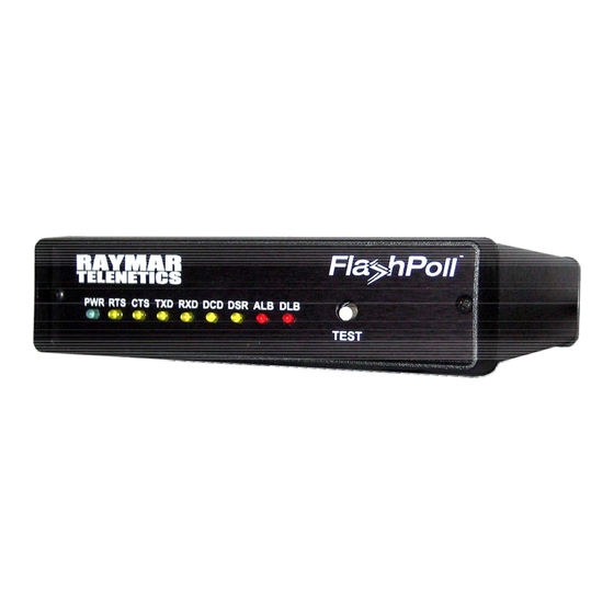
Figure 2-2 Back View of Model DSP9612-LV Modem Front View The Model DSP9612FP and Model DSP9612-LV modems have identical front panels. Figure 2-3 shows the front view of the modem. Starting from the left side, this view shows: A set of nine LEDs. -
Page 13: Installation Summary
Note: Raymar-Telenetics also offers a rack-mount version of this modem (Model DSP9612RM) as a plug-in module for the Telenetics/UDS RM16M Central Site Modem Rack. For more information, contact Raymar-Telenetics Sales Department at 916-783-1951. 0049-0117-100 DSP9612 Flash Poll Modem – User Guide 10/12/2011 Rev. F1 Page 12 of 44... -
Page 14: Configuring The Modem
Use DIP switch 1 (SW1) to select the modem’s transmitter output level and receiver dynamic range. The SW1 settings apply for both high-speed fast-poll and low-speed (FSK) modes. 0049-0117-100 DSP9612 Flash Poll Modem – User Guide 10/12/2011 Rev. F1 Page 13 of 44... -
Page 15: Sw1 Dip Switch Settings
Range (page 16) SW1-6: TX Cable Equalizer Enabled Disabled (page 16) SW1-7: RX Cable Equalizer Enabled Disabled (page 16) SW1-8: Anti-streaming Active Inactive (page 16) 0049-0117-100 DSP9612 Flash Poll Modem – User Guide 10/12/2011 Rev. F1 Page 14 of 44... - Page 16 −3 dBm −4 dBm −5 dBm −6 dBm −7 dBm −8 dBm −9 dBm −10 dBm −11 dBm −12 dBm −13 dBm −14 dBm +3 dBm 0049-0117-100 DSP9612 Flash Poll Modem – User Guide 10/12/2011 Rev. F1 Page 15 of 44...
- Page 17 ON-to-OFF Request To Send (RTS) transition before proceeding with normal operation. Anti-streaming can be selected in either high-speed or low-speed mode. 0049-0117-100 DSP9612 Flash Poll Modem – User Guide 10/12/2011 Rev. F1 Page 16 of 44...
-
Page 18: Sw2 Dip Switch Settings
RTS-CTS Delay (page 19) SW2-6: FSK CD Delay 23ms (page 20) SW2-7: Remote Loopback Enabled Disabled (page 20) SW2-8: Reserved (Test Test Normal Only) (page 20) 0049-0117-100 DSP9612 Flash Poll Modem – User Guide 10/12/2011 Rev. F1 Page 17 of 44... - Page 19 2-wire half-duplex operation (SW3-7 ON) Setting this switch to OFF configures the modem to enable its receiver immediately after the Request To Send (RTS) signal is turned off. 0049-0117-100 DSP9612 Flash Poll Modem – User Guide 10/12/2011 Rev. F1 Page 18 of 44...
- Page 20 Table 2-4. RTS-CTS Delay Settings in Bell 202 Mode To Select Set SW2-4 And Set SW2- a Delay to… 5 to… of… 33ms 59ms 219ms 0049-0117-100 DSP9612 Flash Poll Modem – User Guide 10/12/2011 Rev. F1 Page 19 of 44...
- Page 21 SW2-8 − Reserved (Test Only) SW2-8 Must be OFF SW2-8 must be in the OFF position for normal operation. 0049-0117-100 DSP9612 Flash Poll Modem – User Guide 10/12/2011 Rev. F1 Page 20 of 44...
-
Page 22: Sw3 Dip Switch Settings
SW3-8: Carrier Control Constant Switched (page 25) 600 Ω SW3-9: Rx Termination High Rx Impedance SW3-10: Signal Ground Connected Separated and Earth Ground Option (page 25) 0049-0117-100 DSP9612 Flash Poll Modem – User Guide 10/12/2011 Rev. F1 Page 21 of 44... - Page 23 When they are, both the local and remote modems’ DRS signal should change states. 0049-0117-100 DSP9612 Flash Poll Modem – User Guide 10/12/2011 Rev. F1 Page 22 of 44...
- Page 24 The transmitter turns off if no TXD is detected after 1 character length of idle time. Auto RTS is used in fast-poll mode only (SW3-1 set to OFF). 0049-0117-100 DSP9612 Flash Poll Modem – User Guide 10/12/2011 Rev. F1 Page 23 of 44...
- Page 25 SW3-7 − 2-/4-Wire Operation SW3-7 ON = 2-Wire, Half-Duplex Mode OFF = 4-Wire, Full-Duplex Mode SW3-7 configures the modem for 4-wire full-duplex or 2-wire half-duplex operation. 0049-0117-100 DSP9612 Flash Poll Modem – User Guide 10/12/2011 Rev. F1 Page 24 of 44...
- Page 26 OFF, the receiver is not terminated. SW3-10 − Grounding Option SW3-10 ON = Signal Ground and Earth Ground are Connected OFF = Signal Ground and Earth Ground are Separated 0049-0117-100 DSP9612 Flash Poll Modem – User Guide 10/12/2011 Rev. F1 Page 25 of 44...
-
Page 27: Connecting To A Transmission Line
The modem does not support leased-line Note: operations with DC current. Table 2-7. Transmission Line Connector Pin Assignments This Pin Corresponds to This Number… Signal… RM Model RJ45 0049-0117-100 DSP9612 Flash Poll Modem – User Guide 10/12/2011 Rev. F1 Page 26 of 44... -
Page 28: Connecting To A Voltage Source
Model DSP9612FP (AC version): 85 to 265 Volts AC, 50 to 60 Hz, single phase or 85 to 400 VDC Model DSP9612-LV (DC version): 10 to 53 Volts DC. The model DSP9612-LV comes with a shielded power cord for making this connection. -
Page 29: Connecting An Rs-232 Device
RS-232 device (see Figure 2-1 on page 10). This connector accepts a standard connection to a DTE (RTU) that conforms to the pin assignments shown under “RS-232 (DTE) Interface”. 0049-0117-100 DSP9612 Flash Poll Modem – User Guide 10/12/2011 Rev. F1 Page 28 of 44... -
Page 30: Leds
Yellow Modem Ready Red* Analog Loopback Red* Digital Loopback * When the modem is in remote loopback, both the ALB and DLB LEDs go ON. 0049-0117-100 DSP9612 Flash Poll Modem – User Guide 10/12/2011 Rev. F1 Page 29 of 44... -
Page 31: Loopback Control Switch
OFF prevents the modem from participating in a remote digital loopback with another modem. SW2-7 does not prevent the modem from sending a remote digital loopback request to a remote modem. 0049-0117-100 DSP9612 Flash Poll Modem – User Guide 10/12/2011 Rev. F1 Page 30 of 44... - Page 32 Figure 2-4 illustrates these three diagnostics. Figure 2-4. Loopback Diagnostics 0049-0117-100 DSP9612 Flash Poll Modem – User Guide 10/12/2011 Rev. F1 Page 31 of 44...
-
Page 33: Appendix A Troubleshooting
The receive signal level may be below the CD threshold. Set SW1-5 ON to see whether configuring the modem for a −43 dBm threshold resolves the problem. 0049-0117-100 DSP9612 Flash Poll Modem – User Guide 10/12/2011 Rev. F1 Page 32 of 44... -
Page 34: Appendix Bdip Switch Summary
SW1-6: TX Cable Equalizer Enabled Disabled (page 16) SW1-7: RX Cable Equalizer Enabled Disabled (page 16) SW1-8: Anti-streaming Active Inactive (page 16) SW2-1: FSK Mode V.23 Bell 202 0049-0117-100 DSP9612 Flash Poll Modem – User Guide 10/12/2011 Rev. F1 Page 33 of 44... - Page 35 SW3-8: Carrier Control (page Constant Switched 600 Ω SW3-9: Rx Termination High Rx Impedance SW3-10: Signal Ground and Connected Separated Earth Ground Option (page 0049-0117-100 DSP9612 Flash Poll Modem – User Guide 10/12/2011 Rev. F1 Page 34 of 44...
-
Page 36: Appendix C Specifications
8, 33, 59, or 219 ms (Bell 202) 33 ms (V.23) Receiver dynamic range: 0 to –30 dBm or –10 to –43 dBm Operating temperature: -40°C to +85°C 0049-0117-100 DSP9612 Flash Poll Modem – User Guide 10/12/2011 Rev. F1 Page 35 of 44... -
Page 37: Mechanical Specifications
• DSP9612FP (AC version): 85 to 265Volts AC, 50/60 Hz, single phase or 85 to 400 VDC • DSP9612-LV (DC version):10 to 53 Volts DC Surge protection: Leased line, up to 15KV Carrier control: Constant or switched, DIP switch selectable... -
Page 38: Interface Connector Pin Assignments
Interface Connector Pin Assignments Leased Line Terminal Block Pin Assignments This Pin Corresponds to Number… This Signal… RM Model RJ45 Back-to-Back Connection to a Second Modem 0049-0117-100 DSP9612 Flash Poll Modem – User Guide 10/12/2011 Rev. F1 Page 37 of 44... -
Page 39: Rs-232 (Dte) Interface
Storage temperature: -40 to +125 Operating humidity: 5 to 95 %, non-condensing Line Isolation: 3750 V RMS Surge protection: Leased line up to 15K VA 0049-0117-100 DSP9612 Flash Poll Modem – User Guide 10/12/2011 Rev. F1 Page 38 of 44... -
Page 40: Compliances
Compliances The modem is designed to meet the following agency requirements: EMI/RFI: FCC part 15 for Class A computing device Industry Canada (Emissions) 0049-0117-100 DSP9612 Flash Poll Modem – User Guide 10/12/2011 Rev. F1 Page 39 of 44... - Page 41 The user is cautioned that changes and modifications to this equipment without the approval of the manufacturer could void the user’s authority to operate this equipment. 0049-0117-100 DSP9612 Flash Poll Modem – User Guide 10/12/2011 Rev. F1 Page 40 of 44...
- Page 42 This Class A digital apparatus meets all requirements of the Canadian Interference-Causing Equipment Regulations. Cet appareil numerique de la classe A respecte toutes les exigences du Reglement sur le materiel brouilleur du Canada. 0049-0117-100 DSP9612 Flash Poll Modem – User Guide 10/12/2011 Rev. F1 Page 41 of 44...
-
Page 43: Adapting Ac To Dc
0049-0117-100 DSP9612 Flash Poll Modem – User Guide 10/12/2011 Rev. F1 Page 42 of 44... - Page 44 • To ensure prompt service, please write on the RMA form a brief description of the problem you are experiencing with the product. Raymar Information Technology, Inc. 7325 Roseville Road Sacramento, CA 95842 Service Hotline (800) 747-1522 http://support.telenetics.com or e-mail to techsupport@raymarinc.com 0049-0117-100 DSP9612 Flash Poll Modem – User Guide 10/12/2011 Rev. F1 Page 43 of 44...
- Page 45 Currently, Raymar-Telenetics accepts purchase orders or credit cards as payment methods. Repairs currently require 5 – 10 business days and are returned via UPS Ground. 0049-0117-100 DSP9612 Flash Poll Modem – User Guide 10/12/2011 Rev. F1 Page 44 of 44...
Need help?
Do you have a question about the DSP9612 and is the answer not in the manual?
Questions and answers