Advertisement
Model No. WEEVSY2985.0
Serial No.
Write the serial number in the
space above for future reference.
Serial Number Decal (Under Seat)
QUESTIONS?
As a manufacturer, we are com-
mitted to providing complete
customer satisfaction. If you
have questions, or if there are
missing parts, please call:
08457 089 009
Or write:
ICON Health & Fitness, Ltd.
Unit 4
Revie Road Industrial Estate
Revie Road
Beeston
Leeds, LS118JG
UK
email: csuk@iconeurope.com
CAUTION
Read all precautions and instruc-
tions in this manual before using
this equipment. Save this manual
for future reference.
USER'S MANUAL
Advertisement
Table of Contents

Subscribe to Our Youtube Channel
Related Manuals for Weider Pro 5000


Summary of Contents for Weider Pro 5000
- Page 1 Model No. WEEVSY2985.0 Serial No. USER’S MANUAL Write the serial number in the space above for future reference. Serial Number Decal (Under Seat) QUESTIONS? As a manufacturer, we are com- mitted to providing complete customer satisfaction. If you have questions, or if there are missing parts, please call: 08457 089 009 Or write:...
-
Page 2: Table Of Contents
If the decal is missing or illegible, please call the tele- phone number on the front cover of this manual and order a free replacement decal. WEIDER is a registered trademark of ICON IP, Inc. -
Page 3: Important Precautions
IMPORTANT PRECAUTIONS WARNING: To reduce the risk of serious injury, read the following important precautions before using the weight system. 1. Read all instructions in this manual and all 8. Inspect and properly tighten all parts regular- warnings on the weight system before using ly. -
Page 4: Before You Begin
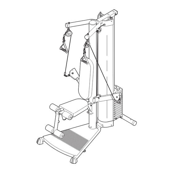
BEFORE YOU BEGIN Thank you for selecting the versatile WEIDER ® reading this manual, see the front cover of this manu- 5000 weight system. The weight system offers a selec- al. To help us assist you, please note the product tion of weight stations designed to develop every model number and serial number before calling. -
Page 5: Assembly
ASSEMBLY • Tighten all parts as you assemble them, unless Make Things Easier for Yourself instructed to do otherwise. Everything in this manual is designed to ensure • As you assemble the weight system, make sure that the weight system can be assembled suc- all parts are oriented as shown in the drawings. - Page 6 2. Press the 110mm Round Inner Cap (42) into the Upright (3). Set the Upright (3) onto the Base (1). Have a sec- ond person hold the Upright until this step is com- pleted. Attach the Upright (3) to the Base (1) with the three M8 x 45mm Bolts (57), three M8 Nylon Locknuts (74), and four M10 x 25mm Screws (58).
- Page 7 4. Insert the Weight Tube (11) into a Weight (17). Make sure the indicated slot in the Weight is oriented as shown. Centre the Roll Pin (54) into the indicated hole in the Weight Tube. Note: The Roll Pin must be below the Weight. Slot 5.
- Page 8 6. Slide an M6 Washer (78) onto the M6 x 127mm Screw (79) and insert the Screw into the Upright (3) through the indicated hole. Set the Shroud (13) onto the Base (1). Attach the Bottom Cover (14) and the Shroud to the Base with two M4 x 16mm Screws (70).
- Page 9 8. Attach the Press Arm (8) without the wire to the Upright (3) with four M10 x 25mm Screws (58). Remove the M4 x 5mm Screw (69) and the Swivel Arm (16). Route the Press Arm Cable (30) through the Swivel Arm and the Press Arm (8) as shown.
- Page 10 11. Wrap the Press Arm Cable (30) around a 3 1/2” Pulley (24) and route the Cable through the Top Cover (15) as shown. Attach the 3 1/2” Pulley (24) and a Cable Trap (28) to the Top Frame (4) with an M10 x 45mm Bolt (65) and an M10 Nylon Locknut (73).
- Page 11 14. Wrap the Press Arm Cable (30) over a 3 1/2” Pulley (24). Attach the Pulley and a Cable Trap (28) to the Top Frame (4) with an M10 x 45mm Bolt (65) and an M10 Nylon Locknut (73). Make sure the Cable Trap is oriented to hold the Cable in the groove of the Pulley.
- Page 12 17. Attach a 2 3/4” Pulley (23) to the right Press Arm (8) with an M10 x 53mm Button Bolt (61), two M10 Washers (71), two 5mm Spacers (25), two Finger Guards (27), and an M10 Nylon Locknut (73). See the inset drawing. Orient the finger guards and pulley as shown.
- Page 13 20. Attach the Seat (19) to the Seat Frame (6) with two M6 x 16mm Screws (60), an M6 x 77mm Screw (68), and an M6 Washer (78). Hook the Seat Frame (6) onto the Upright (3) at the indicated location. 21.
-
Page 14: Adjustments
ADJUSTMENTS This section explains how to adjust the weight system. See the EXERCISE GUIDELINES on page 18 for impor- tant information about how to get the most benefit from your exercise program. Also, refer to the accompanying exercise guide to see the correct form for each exercise. Make sure all parts are properly tightened each time the weight system is used. - Page 15 ADJUSTING THE SEAT FRAME HEIGHT To adjust the height of the Seat Frame (6), or to remove it for exercising with the squat bar, unhook the Seat Frame from the indicated brackets on the Upright (3). Hook it onto the other bracket or set it aside.
-
Page 16: Cable Diagram
ATTACHING THE LEG LEVER To use the Leg Lever (7), first attach the seat to the resistance system (see ADJUSTING THE SEAT FRAME HEIGHT on page 15). Then, attach the pulley housings to the low pulley station (see ATTACHING THE PULLEY HOUSINGS on page 14). Finally, attach the Extension Cables (31) to an Extension Strap (34) with two Cable Clips (37) and attach the Extension Strap to the Leg Lever with another Cable Clip. -
Page 17: Weight Resistance Chart
WEIGHT RESISTANCE CHART The chart below shows the approximate weight resistance for the 12.5 lb. (5.67 kg.) weights. Weight resistance shown is for each arm. Note: The actual resistance at each station may vary due to differences in individ- ual weight plates as well as friction between the cables, pulleys, and weight guides. WEIGHT RESISTANCE (Note: 1 lb. -
Page 18: Exercise Guidelines
EXERCISE GUIDELINES THE FOUR BASIC TYPES OF WORKOUTS PERSONALISING YOUR EXERCISE PROGRAM Muscle Building Determining the exact length of time for each workout, To increase the size and strength of your muscles, as well as the number of repetitions or sets completed, push them to a high percentage of their maximum is an individual matter. - Page 19 Rest for a short period of time after each set. The slowly as you stretch and do not bounce. Ease into ideal resting periods are: each stretch gradually and go only as far as you can • Rest for three minutes after each set for a muscle without strain.
-
Page 20: Ordering Replacement Parts
Please provide the following information when ordering replacement parts: • the MODEL NUMBER of the product (WEEVSY2985.0) • the NAME of the product (WEIDER PRO 5000 weight system) • the SERIAL NUMBER of the product (see the front cover of this manual) •... - Page 21 PART LIST—Model No. WEEVSY2985.0 R0805A Key No. Qty. Description Key No. Qty. Description Base 32mm Round Inner Cap Base Plate 51mm x 76mm Inner Cap Upright M4 x 40mm Screw Top Frame 25mm Spacer Rear Stabiliser 38mm Spacer Seat Frame Bumper Leg Lever Weight Bumper...
- Page 22 PART IDENTIFICATION CHART Refer to the drawings below to identify small parts used in assembly. The number in parentheses by each draw- ing is the key number of the part, from the PART LIST in the centre of this manual. Note: Some small parts may have been pre-attached.
- Page 23 EXPLODED DRAWING—Model No. WEEVSY2985.0 R0805A 24 28 24 28...
- Page 24 EXPLODED DRAWING—Model No. WEEVSY2985.0 R0805A 49 70...
Need help?
Do you have a question about the Pro 5000 and is the answer not in the manual?
Questions and answers