TRENDnet ProView TV-IP512P User Manual
Poe network camera
Hide thumbs
Also See for ProView TV-IP512P:
- Quick installation manual (15 pages) ,
- Quick installation manual (15 pages)
Table of Contents
Advertisement
Quick Links
Advertisement
Table of Contents

Related Manuals for TRENDnet ProView TV-IP512P


Summary of Contents for TRENDnet ProView TV-IP512P
-
Page 2: Table Of Contents
CONTENTS About This User’s Guide ....................... iv Before You Start ..........................iv Packing List ........................... iv System Requirements ........................v Default Settings ..........................vi INTRODUCTION ........................7 Features and Benefits ........................7 Camera Hardware Components ..................... 8 Front Panel Components ....................... 8 LED Indicators .......................... - Page 3 Play Video Files ..........................61 ffdshow ............................62 TECHNICAL SPECIFICATIONS ..................68 I/O TERMINAL APPLICATION ..................71...
-
Page 4: About This User's Guide
TV-IP512P ProView PoE Internet Camera About This User’s Guide This user’s guide provides instructions on how to install the TV-IP512P PoE Network Camera and use it for camera monitoring applications. Camera monitor applications are accessible through an Ethernet local area network. -
Page 5: System Requirements
TV-IP512P ProView PoE Internet Camera System Requirements Computer • CPU: o For Intel x86 compatible CPUs: Intel Pentium IV 2.0Ghz or above o For IA64 compatible CPUs: AMD Athlon 64 3000+ and above • Memory: 1GB or above • VGA Resolution: 1024 x 768 or above (Independent Display Card recommended) •... -
Page 6: Default Settings
Use the default settings to access the web-based management software and live video display. Default configuration settings Username This is the Username you will be prompted to enter when you access the TV-IP512P configuration screens using a Web browser. The default Username is admin. Password This is the Password you will be prompted to enter when you access the configuration windows using a Web browser. -
Page 7: Introduction
TV-IP512P ProView PoE Internet Camera Introduction The TV-IP512P PoE Network Camera transmits live real-time high-quality MPEG-4 video through an Ethernet network useful for remote monitoring applications. The live video can be viewed remotely and managed through the network from any computer connected to the network. -
Page 8: Camera Hardware Components
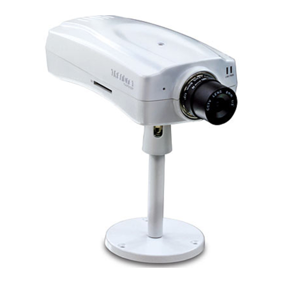
TV-IP512P ProView PoE Internet Camera Camera Hardware Components Below is a summary description of the camera hardware: Front Panel Components Adjustable focus camera lens Link LED indicator Power LED indicator Audio mic Front panel of TV-IP512P LED Indicators This LED indicator lights steady orange when a valid Ethernet link is established. -
Page 9: Rear Panel Components
TV-IP512P ProView PoE Internet Camera Rear Panel Components The power connection to the camera when fitted with the Infrared lens is split between the camera body and lens using the power connection adapter cable attached to the infrared lens. All other cables connect to the camera at the rear panel. -
Page 10: Installing The Camera
TV-IP512P ProView PoE Internet Camera Installing the Camera The camera should be attached to the stand included in the package. The camera stand can be mounted on a flat surface using the three screw holes on the base of the stand. The camera is intended for indoor use. -
Page 11: Connect Ethernet Cable
TV-IP512P ProView PoE Internet Camera Connect Ethernet Cable To connect the camera to your network, connect a Category 5 or better Ethernet cable to the network cable connector located on the camera’s left side panel, and then attach it to the network. The Ethernet... -
Page 12: Connect Power Using Poe
The diagram below shows you how to connect the TV-IP512P camera to a PoE enabled switch: If the switch or router you are connecting the TV-IP512P camera to does not support PoE, a power injector can be connected between the TV-IP512P Camera and the switch/router as shown in the... -
Page 13: Reset Camera
TV-IP512P ProView PoE Internet Camera Reset Camera A manual reset can be conducted by following the procedure below. The reset button is located on the rear panel of the camera. To reset the system settings to factory defaults, please follow these steps: 1. -
Page 14: Setupwizard
Once the software is installed, the SetupWizard utility is ready for use. Launching the SetupWizard To launch the SetupWizard, click Start > Programs > TRENDnet > SetupWizard > SetupWizard. SetupWizard- Install Your Camera Connect the camera to your LAN using the provided RJ45 cable. - Page 15 TV-IP512P ProView PoE Internet Camera SetupWizard- Select Your Camera The following screen appears showing the cameras that have been found on your network: Click on the camera you want to configure. Click Next to continue.
- Page 16 TV-IP512P ProView PoE Internet Camera SetupWizard- Authentication On the following screen type in the ID and Password that you will use to configuring the camera settings: Type a User ID in the ID field. Type the password of the User in the Password field.
- Page 17 TV-IP512P ProView PoE Internet Camera SetupWizard- Change Password The following screen allows you to change the default admin password: Carry out the following if you want to change the admin password: Tick the Change Password checkbox Type in a New Password in the New Password field and confirm it in the Confirm...
- Page 18 TV-IP512P ProView PoE Internet Camera SetupWizard- Select a Connection Option The following window allows you to specify the connection method used by your camera network. Click the radio button of the network environment your camera is connected to. The available...
- Page 19 TV-IP512P ProView PoE Internet Camera SetupWizard- Select a Connection Option- PPPoE If your connection method is PPPoE, click the PPPoE radio button and click Next: The following window appears: Type the User Name used to connect to your PPPoE connection in the User Name field.
- Page 20 TV-IP512P ProView PoE Internet Camera SetupWizard- Select a Connection Option- DHCP If your connection method is DHCP, click the DHCP radio button and click Next:...
- Page 21 TV-IP512P ProView PoE Internet Camera SetupWizard- Select a Connection Option- Fixed IP If your connection method is Fixed IP, click the Fixed IP radio button: The following window appears: Type in the IP Address, Subnet Mask, Default Gateway, Primary DNS Server IP address and Secondary DNS Server IP Address in the appropriate fields.
- Page 22 TV-IP512P ProView PoE Internet Camera SetupWizard- Other Settings The following window allows you to configure additional camera settings: Type a name to help you identify the camera in the Camera Name field. Set the camera date and time from the Camera Time drop-down menus. To use the time settings from your computer, click the Copy Local Time button.
- Page 23 TV-IP512P ProView PoE Internet Camera SetupWizard- Setting Up The Camera The following window appears, summarizing the network settings of your camera: When you have finished setting up the Camera click the Next button. To make any changes to your Camera settings, click the Previous button.
- Page 24 TV-IP512P ProView PoE Internet Camera SetupWizard- Complete After the camera has restarted, the following window will appear: Click the hyper-link to connect to the camera web interface. If you want to setup an additional camera, click the Setup Another Camera button.
-
Page 25: Using The Camera Web Manager
For the initial setup, use the SetupWizard program located on the TV-IP512P CD-ROM included with the camera. Use the IPCam Wizard to assign an IP address and other network settings. Once the camera has an IP address, follow the instructions below to access the camera’s web... -
Page 26: Login
TV-IP512P ProView PoE Internet Camera Login To access the web manager directly from a computer or on a network without a DHCP server running, use the default IP address of the camera in the browser address entry to access the web manager. Type http://192.168.10.30 in the address bar and press Enter. -
Page 27: Live Video Display User Interface
TV-IP512P ProView PoE Internet Camera Live Video Display User Interface The web manager’s live video page presents icons at the bottom used to change the display size, control snapshot and recording of video and audio controls. Links to other management menus are located at the top right porting of the interface. - Page 28 TV-IP512P ProView PoE Internet Camera Recording, Snapshot, Audio and Digital Output Controls Record and Snapshot Use the camera icon to take a snapshot of the video display. This will immediately cause the screen capture or snapshot to appear on the desktop in a new browser window. Use the Record (REC) icon to begin recording to the local hard disk.
-
Page 29: Camera Configuration Setup
TV-IP512P ProView PoE Internet Camera Camera Configuration Setup Click the CONFIGURATION link to view the menus in the Configuration Menu directory. These menus are used to configure network settings, video and other settings for the camera. SetupWizard menu in Configuration directory To configure the camera with the web manager’s SetupWizard, click the Next button and follow the... -
Page 30: Network Settings
TV-IP512P ProView PoE Internet Camera Network Settings Click the Network Setup link to view menus for IP network settings, PPPoE configuration, DDNS and HTTP or RTSP port configuration. Network Setup menus LAN IP Settings The camera’s IP settings can be configured as a DHCP client to obtain IP settings automatically, or configure static IP settings as needed for the private network. - Page 31 TV-IP512P ProView PoE Internet Camera UPnP If you want to enable the TV-IP512P PoE Network Camera to connect to other UPnP devices in your network, tick the Enable UPnP checkbox. UPnP port forwarding To enable UPnP port forwarding, tick the Enable UPnP port forwarding checkbox. Enabling UPnP port forwarding allows the camera to add a port forwarding entry to be added to your router automatically.
-
Page 32: Image Setup
TV-IP512P ProView PoE Internet Camera Image Setup Use the Image Setup configuration to optimize the live video display. Video image settings Brightness Adjust the brightness level. The value range is from 0 – 100. (The default setting is 42.) Contrast Adjust the contrast level. -
Page 33: Video And Audio Settings
Reset to Default Click this button to reset the TV-IP512P Image Settings back to factory defaults. Video and Audio Settings Use this menu to configure up to four video profiles. These are used to optimize video encoding type, resolution, frame rate and bit rate settings on the camera for the type of display being used. -
Page 34: Motion Detection
TV-IP512P ProView PoE Internet Camera you to get more ambient light from the background, allowing you to see more detail from both the subject and background of your video/picture. Audio Setup Use the Audio Setup menu to enable and disable the microphone and speaker as well as adjust the volume of each. -
Page 35: Time And Date
TV-IP512P ProView PoE Internet Camera Time and Date Use the Time and Date menu to set the camera’s time settings manually, from the computer’s time or use a network time server (NTP server). Time and date menu Time Zone Use the drop-down menu to select your time zone. - Page 36 TV-IP512P ProView PoE Internet Camera Automatic time configuration Click a radio button to specify the method used to set the time on the TV-IP512P. Synchronize with NTP Server Click this radio button to specify that the TV-IP512P should be synchronized with an NTP Server.
-
Page 37: Recording
Server- Type the name or IP address of the server your Samba drive is on. Shared Folder- Enter the path that points to the shared server. Recording Menu Click the Test button to check that the TV-IP512P can connect to the Samba drive. - Page 38 TV-IP512P ProView PoE Internet Camera Snapshot Preferences The Trigger menu is used to determine when and how recorded digital images from snapshots are handled. Use motion detection to trigger a snapshot and email it to the account configured here. Alternatively, the images can be sent to an FTP server.
- Page 39 Port- Enter the port number that will be used to send the snapshot e-mails. Test- Click this button to send a test e-mail from the TV-IP512P to the specified recipient e-mail address to verify that all the credentials have been configured correctly.
- Page 40 TV-IP512P ProView PoE Internet Camera Digital images can also be sent to any display running the User Interface during the event. To enable this use the Digital Output menu (see below). Digital Output Use this menu to enable digital output triggered by motion detection or an input signal through the I/O terminal.
- Page 41 TV-IP512P ProView PoE Internet Camera RS-485 RS-485 control is used to enable use of external devices (such as motorized rotational or pan and tilt camera stand) operated through the I/O port. Note: 485+/- of the I/O connector are used for RS-485. Refer to the manufacturer’s user manual for proper connection instructions.
-
Page 42: System Configuration
TV-IP512P ProView PoE Internet Camera System Configuration The System configuration menus include the Device Management menu. Device Management menu Admin Password Setting Use this section to change the Admin Password for the camera. Type in a New Password and confirm it in the Retype Password field. Click Save to set the new password. - Page 43 TV-IP512P ProView PoE Internet Camera Add User Account Use this section to add a new user. Up to 20 User accounts can be created on the TV-IP512P camera. To create a new user, carry out the following: Type a name for the new user in the User Name field.
-
Page 44: Back Up And Restore Camera Settings
TV-IP512P ProView PoE Internet Camera Back Up and Restore Camera Settings Save System Settings/Restore/Reboot menu Save To Local Hard Drive To save configuration settings for the camera to a file on a local hard disk, click the Save Configuration button. A prompt appears to confirm that you want to save the file. Choose the location and save the file to load the same settings. -
Page 45: Firmware Upgrade
TV-IP512P ProView PoE Internet Camera Firmware Upgrade To upgrade the camera firmware, make sure the correct firmware file is located on your computer. Click the Browse button to locate the file. After locating the file, click the Upload button to load the file. -
Page 46: Device Information
TV-IP512P ProView PoE Internet Camera Device Information Network information, MAC address and firmware version is displayed in the Device Information display. Device Information display Click the Log link to view the camera’s current log. To save the log in simple text form on your computer, click the Download button. -
Page 47: Ipview Pro 2.0
Launching IPView Pro 2.0 for the first time To launch IPView Pro 2.0, click Start > Programs > TRENDnet > IPView Pro 2.0 > IPView Pro 2.0. If this is the first time using the software, the menu that appears is the Add camera menu:... - Page 48 TV-IP512P ProView PoE Internet Camera Add a camera for monitoring The Add camera menu is presented the first time the IPView Pro 2.0 software is launched. This menu is used to add cameras to the user interface for monitoring. After the first time running the software, this menu can be accessed at anytime from the Configuration menus.
- Page 49 TV-IP512P ProView PoE Internet Camera If the camera does not appear listed, click the Input the location of camera tab above the list to view a new menu. Enter the IP address or the URL (for example, ipcam.ddns.org) of the camera being added, type the user name and password and click the Preview to verify that a link can be established.
-
Page 50: Ipview Pro 2.0 User Interface
TV-IP512P ProView PoE Internet Camera IPView Pro 2.0 User Interface Below is a general description of the user interface. Item Description Live video display Display area for single or multiple cameras of live video. Right click on area any display area to view a list of quick configure options for that camera including the “Replace camera content …”... - Page 51 TV-IP512P ProView PoE Internet Camera Display Controls The primary display and IPView Pro 2.0 control icons are described in detail below. When there are more than one camera displays viewed, one of the displays can be selected for management or additional changes. Simply left click on any display to select it. Notice the border around the display is bright aqua blue, indicating the “selected”...
- Page 52 TV-IP512P ProView PoE Internet Camera Live video display controls Use the video display controls to change the view of the live video display. This is useful for multiple camera application. Click the arrows to manually cycle through the active camera’s live displays when using a single camera display screen.
-
Page 53: Camera Configuration With Ipview Pro 2.0
TV-IP512P ProView PoE Internet Camera Camera configuration with IPView Pro 2.0 Access the camera configuration menus by clicking on the gear icon at the bottom of the right hand panel of the IPView Pro 2.0 user interface. Configuration options include adding and deleting cameras from the display view, configuration of motion detection and digital input with schedules, recording options, email alerts and other network settings. -
Page 54: Removing A Camera
TV-IP512P ProView PoE Internet Camera 2. Select the camera to add from the list, enter the administrator’s user name (ID:) and password, a preview of the live video display will appear. Click the OK, add this camera button, a confirmation message informs when the camera is connected and added to the IPView Pro 2.0 monitoring group. -
Page 55: Schedule Recording With Ipview Pro 2.0
TV-IP512P ProView PoE Internet Camera Schedule Recording with IPView Pro 2.0 Use the Monitoring Settings menu to create schedules for recording and apply the schedules to any camera. Click the Monitoring Settings tab to view the Schedule Recording menu (the first menu viewed in the Camera Settings menu tab). -
Page 56: Setup Motion Detection And Digital Input With Ipview Pro 2.0
TV-IP512P ProView PoE Internet Camera Setup Motion Detection and Digital Input with IPView Pro 2.0 The Monitoring Settings Camera Settings menus include Motion Detection setup and Digital Input control. Each menu has the schedule option to apply a schedule for the action taken or always take the specified action. - Page 57 TV-IP512P ProView PoE Internet Camera IPView Pro 2.0 Recording Options The Recording Options configured in the IPView Pro 2.0 help to conserve and manage allowed memory storage (disk space) and for video file management. Recorded files can be limited by time elapsed or by size.
- Page 58 TV-IP512P ProView PoE Internet Camera IPView Pro 2.0 Miscellaneous Options The Other Options available for configuration include Proxy server setup, email notification, scan interval and alert type settings. If you are using a SSL email account(eg. Gmail) to send the images; please select SSL at this...
-
Page 59: Playing Video Files On A Computer
TV-IP512P ProView PoE Internet Camera Playing Video Files on a Computer IPCamPlayer software is installed on the monitoring station or administrator’s system along with the IPView Pro 2.0 monitoring software. Use it to playback and manage recorded video from the cameras added to the IPView Pro 2.0 group. -
Page 60: Load Saved Video Files
My Documents folder in Windows. The file folders are named according to the IP address and camera model. For example, 192.168.10.30_TV-IP512P is the name of the file folder for the TV-IP512P using the default (non-DHCP) IP address. IPCamPlayer User Interface... -
Page 61: Play Video Files
TV-IP512P ProView PoE Internet Camera To view recorded video files in the IPCamPlayer, it is first necessary to locate and select the files to be viewed and add them to the list. Click the Search Files button in the IPCamPlayer main interface and a new menu appears. -
Page 62: Ffdshow
TV-IP512P ProView PoE Internet Camera ffdshow The ffdshow software is used for audio and video encoding and decoding, especially for MPEG-4 formats. It is free software used on Windows systems and enables the user to tweak media playback and select specific codecs and formats. For use with the IPCamPlayer, the default settings used for ffdshow installation are all that is needed. - Page 63 TV-IP512P ProView PoE Internet Camera 4. Accept the default location (Windows Programs folder) on the system for placement or Browse to choose an alternative, Click Next to continue. 5. Click to check the components that will be installed. For IPCamPlayer it is only necessary...
- Page 64 TV-IP512P ProView PoE Internet Camera 6. Accept the default destination folder (ffdshow) or Browse to choose an alternative, Click Next to continue. 7. Click to check the additional tasks that will be installed. For IPCamPlayer it is only necessary to use the default formats already selected. Click Next to continue.
- Page 65 TV-IP512P ProView PoE Internet Camera 8. Click to check the video applications that use ffdshow. For IPCamPlayer it is only necessary to use the default applications already selected. Click Next to continue. 9. Click to check the audio applications that use ffdshow. For IPCamPlayer it is only...
- Page 66 TV-IP512P ProView PoE Internet Camera 10. Choose a speaker setup or choose Disable mixer if unsure. The audio function will work regardless of what speaker setup is chosen. Usually it will choose the default arrangement used on system on which it is being installed. Click Next to continue.
- Page 67 TV-IP512P ProView PoE Internet Camera 12. If desired, any of the three configuration utilities included with the ffdshow installation can be launched by checking the appropriate box. Click Finish to complete the installation. To download the latest copy of ffdshow please check the ffdshow website NOTE: http://ffdshow.en.softonic.com/...
-
Page 68: Technical Specifications
TV-IP512P ProView PoE Internet Camera Technical Specifications Camera General Sensor: 1/4” color CMOS SOC image sensor Resolution: 640 x 480 pixels Lens: 1/3” CS‐Mount, replaceable Focal Length: 6mm F/No: F1.8 Minimum illumination: 0.5 Lux @ F1.8 Minimum Object Distance (M.O.D.): 70cm View angle: diagonal 44 degree Audio Built‐in omni‐directional microphone Sensitivity: ‐48dB +/‐ 3dB (5 meters max) Frequency: 50~16000Hz S/N: 50dB External speaker output Two‐way audio with echo canceling Codec: ARM/PCM Image & Video Compression: MPEG‐4 / MJPEG Profiles: up to 4 profiles simultaneously Exposure/white balance control: automatic Resolution: VGA (640x480), QVGA (320x240), QQVGA (160x120) up to 30fps I/O Connector Input: 2 sets (pin 1/2, pin 3/4) Output: 1 set (pin 5/6) RS‐485: 1 set (pin 7/8) SD slot Secure Digital card (up to 16G) Hardware Network IEEE 802.3u 10/100Mbps Fast Ethernet, Auto‐MDIX IEEE 802.3af PoE ... - Page 69 TV-IP512P ProView PoE Internet Camera LED Power, Link Reset Button Reset settings Power Consumption 9 Watts Power 12V, 1.5A external power adapter Dimension 170 x 80 x 40mm (6.7 x 3.2 x 1.6 in.) Stand Dimension 128 mm (4.7 in.) Weight Camera: 260g (9.2 oz.) Stand: 116g (4.1 oz.) Temperature Operating: 0°C ~ 40°C (39°F ~ 104°F) Storage: ‐15°C ~ 60°C (5°F ~ 140°F) Certification CE, FCC Requirement To View Internet Explorer 6.0 or above To Run Software Windows 7 (32/64‐bit), Vista (32/64‐bit), XP (32/64‐bit) IPView Pro 2.0 Channel: supports up to 32 cameras Record/Playback/Motion Detection/Audio Network Protocols IPV4, ARP, TCP, UDP,ICMP DHCP Client, NTP Client, DNS Client, DDNS Client, SMTP Client, FTP Client HTTP Server Samba Client PPPoE UPnP AV ...
- Page 70 TV-IP512P ProView PoE Internet Camera Video Profile 1‐2 ‐ Encoding type: MPEG‐4 and MJPEG ‐ Resolution: 640 x 480, 320 x 240, 160 x 120 ‐ Frame rate: 1, 2, 3, 5, 10, 15, 30 ‐ Fixed bit rate: 64k, 128k, 256k, 384k, 512k, 768k, 1M, 1.5M, 2M Profile 3 ‐ Encoding type: MJPEG ‐ Resolution: 640 x 480, 320 x 240, 160 x 120 ‐ Frame rate: 1, 2, 3, 5, 10, 15, 30 ‐ Fixed bit rate: 64k, 128k, 256k, 384k, 512k, 768k, 1M, 1.5M, 2M Profile 4 (for mobile device only) ‐ Encoding type: MPEG‐4 ‐ Resolution: 640 x 480, 320 x 240, 160 x 120 ‐ Frame rate: 1, 2, 3, 5, 10, 15, 30 ‐ Fixed bit rate: 64k, 128k, 256k, 384k, 512k, 768k, 1M, 1.5M, 2M Recording Resolutions: 4 profiles Storage size: 32MB (minimum) Recording type: event based (motion detection and digital input trigger), continuous and scheduled Snapshot Trigger event: motion detection or digital input signal ...
-
Page 71: I/O Terminal Application
TV-IP512P ProView PoE Internet Camera I/O Terminal Application Typically used in association with programming scripts for developing applications for motion detection, event triggering, alarm notification via e-mail, and a variety of external control functions. The 8-pin I/O Terminal Block is located on the rear panel and provides the interface of a photo- coupled switch output and a photo-coupled input. - Page 72 TV-IP512P ProView PoE Internet Camera Interface Schematic 1. Output device (load) is driven by external power supply. AC/ DC Load 2. Input device (active control device) has independent power supply. 3. RS-485 Interface. RS-485+ RS485_A RS-485- RS485_B Swivel stand...
-
Page 73: Limited Warranty
TV-IP512P ProView PoE Internet Camera Limited Warranty TRENDware warrants its products against defects in material and workmanship, under normal use and service, for the following lengths of time from the date of purchase. TV-IP512P – 3 years warranty If a product does not operate as warranted above during the applicable warranty period, TRENDware shall, at its option and expense, repair the defective product or part, deliver to customer an equivalent product or part to replace the defective item, or refund to customer the purchase price paid for the defective product. - Page 74 Download section and look for the desired TRENDnet product to access to the GPL Code or LGPL Code. These codes are distributed WITHOUT WARRANTY and are subject to the copyrights of the developers. TRENDnet does not provide technical support for these codes. Please go to http://www.gnu.org/licenses/gpl.txt...
- Page 75 TV-IP512P ProView PoE Internet Camera...
Need help?
Do you have a question about the ProView TV-IP512P and is the answer not in the manual?
Questions and answers