Table of Contents
Advertisement
Quick Links
Advertisement
Table of Contents

Related Manuals for TRENDnet TV-IP501P


Summary of Contents for TRENDnet TV-IP501P
- Page 1 TV-IP501P Internet Camera User Manual...
-
Page 2: Table Of Contents
TV-IP501P Internet Camera User Manual Table of Contents Table of Contents ............................1 Before you start ............................3 Packing List ..............................3 System Requirements ..........................4 Default Settings ............................4 Introduction ..............................5 Features and Benefits ......................... 5 Camera Hardware Components ......................... 6 ... - Page 3 TV-IP501P Internet Camera User Manual Upload .............................. 24 E-Mail ..............................25 Tools Section ............................ 26 FTP Server Test ..........................26 E-Mail Test ............................26 Restart .............................. 27 Factory Reset ........................... 27 Firmware Upgrade ..........................27 Backup and Restore ......................... 28 ...
-
Page 4: Before You Start
TV-IP501P Internet Camera User Manual About this User’s Guide This user’s guide provides instructions on how to install the TV-IP501P PoE Internet Camera and use it for camera monitoring applications. Camera monitor applications are accessible through an Ethernet local area network. -
Page 5: System Requirements
TV-IP501P Internet Camera User Manual System Requirements Computer CPU: For Intel x86 compatible CPUs: Intel Pentium IV 2.0Ghz or above CPU: For IA64 compatible CPUs: AMD Athlon 64 3000+ and above Memory: 1GB or above VGA Resolution: 1024 x 768 or above (Independent Display Card recommended) -
Page 6: Introduction
TV-IP501P Internet Camera User Manual Introduction The TV-IP501P PoE Internet Camera transmits live real-time high-quality MPJEG video through an Ethernet network useful for remote monitoring applications. The live video can be viewed remotely and managed through the network from any computer connected to the network. -
Page 7: Camera Hardware Components
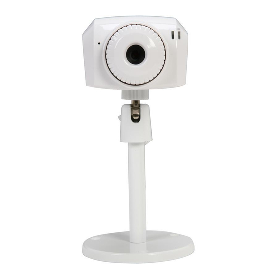
TV-IP501P Internet Camera User Manual Camera Hardware Components Front Components Rear Panel Components All cables connect to the camera at the rear panel. -
Page 8: Led Indicators
TV-IP501P Internet Camera User Manual Camera Hardware Components Below is a summary description of the camera hardware. Audio Mic Used to capture sounds DC 5V The DC power input connector is located on the back of the camera’s rear panel and is labeled DC5V with a single jack socket to supply power to the camera. -
Page 9: Hardware Installation
TV-IP501P Internet Camera User Manual Hardware Installation The camera can be attached to the included stand and placed on a sturdy flat surface or hung from a ceiling or similar flat surface. Mounting of Camera Determine the location for the camera and assemble the camera stand. Secure the stand to the flat surface or ceiling with the mounting screws included in the package. -
Page 10: Connect Ethernet Cable
The diagram below shows you how to connect the TV-IP501P camera to a PoE enabled switch. If the switch or router you are connecting the TV-IP501P camera to does not support PoE, a power injector can be connected between the TV-IP501P Camera and the switch/router as shown in the... -
Page 11: Reset Camera
TV-IP501P Internet Camera User Manual Reset Camera A manual reset can be conducted by following the procedure below. The reset button is located on the rear panel of the camera. To reset the system settings to factory defaults, please follow these steps: Leave the camera powered on, do not disconnect the power. -
Page 12: Software - Setup Wizard
Once the software is installed, the Setup Wizard utility is ready for use. Launching Setup Wizard for the first time To launch the Setup Wizard, click Start > Programs > TRENDnet > Setup Wizard > Setup Wizard Install Your Camera Connect the camera to your LAN using the provided RJ45 cable. - Page 13 TV-IP501P Internet Camera User Manual Authentication On the following screen type in the ID and Password that you will use to configuring the camera settings. Type a User ID in the ID field. Type the password of the User in the Password field.
- Page 14 TV-IP501P Internet Camera User Manual Select a Connection Option- PPPoE If your connection method is PPPoE, click the PPPoE radio button and click Next. The following window appears. Type the User Name used to connect to your PPPoE connection in the User Name field.
- Page 15 TV-IP501P Internet Camera User Manual Setting Up The Camera The following window appears, summarizing the network settings of your camera. When you have finished setting up the Camera click the Next button. To make any changes to your Camera settings, click the Previous button.
-
Page 16: Web Configuration
TV-IP501P Internet Camera User Manual Browser Configuration The camera is easy to use and manage using a web browser or the IPViewPro 2.0 software to access the camera’s live video display, and configuration software. Check and make sure the computer can access and use the camera before placing it in the location where it will be used, especially if it is mounted to a ceiling or other difficult to access area. -
Page 17: Login
TV-IP501P Internet Camera User Manual Login To access the web manager directly from a computer or on a network without a DHCP server running, use the default IP address of the camera in the browser address entry to access the web manager. Type http://192.168.10.30 in the address bar and press Enter. -
Page 18: Video - Activex
TV-IP501P Internet Camera User Manual Video – ActiveX To view live video from browser, using ActiveX, click the View Video-ActiveX Mode from the Welcome screen to access the live video feed : Video – Java To view live video from... - Page 19 TV-IP501P Internet Camera User Manual As you can see, both live video display pages are identical both in look and the controls that are available to manage the display. Video Display Control The Zoom option allows you to digitally zoom in on an object up to 4...
-
Page 20: Administration - Status Section
TV-IP501P Internet Camera User Manual Administration - Status Section The Status section displays information about the camera. In the Status section there are pages for System, Video, Audio, Network and Active Users. System Page The System Page display information about the Device Status and Ethernet Status of the camera. -
Page 21: Audio
TV-IP501P Internet Camera User Manual Audio The Video page displays information about the audio configuration of the camera like Audio Enabled or Disabled, Audio Volume Level, Codec and Sample rate. Network The Network page display the network configuration for the camera like IP Address, Subnet Mask, Default gateway, Primary and Secondary DNS Addresses, Dynamic DNS Enabled or Disabled, Secondary HTTP Port value, UPnP IP Address, FTP Server and E-Mail setup. -
Page 22: Configuration Section
TV-IP501P Internet Camera User Manual Configuration Section In the configuration you can set the configuration for the camera. System On the Status Page you can configure general system settings for the camera. Camera Name: Configure the camera’s display name. Location: Configure the camera’s display location. -
Page 23: Video
TV-IP501P Internet Camera User Manual Video On the Video page you can configure the video display settings for the camera. Video Resolution: Select between 3 different Video Resolutions. Compression Rate: Select between 5 different Compression Rates. Frame Rate: Select between 5 different Frame Rates Choose Auto to let the camera choose the best frame rate needed. -
Page 24: Network
TV-IP501P Internet Camera User Manual Network Click the Network Setup link to view menus for IP network settings, PPPoE configuration, DDNS and HTTP or RTSP port configuration. Fixed IP: Selecting Static IP Configuration requires you to assign IP information for the camera manually. -
Page 25: User
TV-IP501P Internet Camera User Manual User On the User page you can create or delete users. Access Control: Here you can enable or disable user access control. Define User: Here you can add user accounts. Delete User: Here you can remove user accounts. -
Page 26: E-Mail
TV-IP501P Internet Camera User Manual E-Mail On this page you can setup the e-mail client configuration that the camera can use. SMTP Server Address: Enter the Mail Server IP address here. SMTP Port Number: Enter the SMTP port number used here. -
Page 27: Tools Section
TV-IP501P Internet Camera User Manual Tools Section The Tools section offers many features to test FTP server settings E-Mail settings Firmware upgrade, Backup settings and Restart or Restore options. FTP Server Test This page will help the user to test if the FTP server settings are setup correctly. It will send a JPEG file to the FTP server called ‘test_date_time.jpg’... -
Page 28: Restart
TV-IP501P Internet Camera User Manual Restart This page gives you the option to manually restart the camera. Factory Reset This page gives you the option the factory reset your camera through its web configuration. Firmware Upgrade This page gives you the option to upgrade the firmware for the camera. To upgrade the firmware you’ll need to download the latest firmware for your camera to your computer, click on the Browse button, navigate to the downloaded file and click Upgrade. -
Page 29: Backup And Restore
TV-IP501P Internet Camera User Manual Backup and Restore This page will allow the user to backup the configuration of the camera to a file that can be saved remotely. It also gives the option to restore the settings from the backup file saved on the hard drive. -
Page 30: Software - Ipviewpro 2.0
Launching IPViewPro 2.0 for the first time To launch IPViewPro 2.0, click Start > Programs > TRENDnet > IPViewPro 2.0. If this is the first time using the software, the menu that appears on is the Add camera menu. -
Page 31: Add A Camera For Monitoring
TV-IP501P Internet Camera User Manual Add a camera for monitoring The Add camera menu is presented the first time the IPViewPro 2.0 software is launched. This menu is used to add cameras to the user interface for monitoring. After the first time running the software, this menu can be accessed at anytime from the configuration menus. -
Page 32: Ipviewpro 2.0 User Interface
TV-IP501P Internet Camera User Manual IPViewPro 2.0 User Interface Below is a general description of the user interface. Item Description Live video display area Display area for single or multiple cameras of live video. Right click on any display area to view a list of quick configure options for that camera including the “Replace... -
Page 33: Display Controls
TV-IP501P Internet Camera User Manual on box to select camera display. The status indicators for each camera display recording, motion detection and GP input status. Camera information Displays basic information on selected camera. Display Controls The primary display and IPViewPro 2.0 control icons are described in detail below. When there are more than one camera displays viewed, one of the displays can be selected for management or additional changes. -
Page 34: Snapshot, Recording And Audio Controls
TV-IP501P Internet Camera User Manual Snapshot, recording and audio controls The still photo camera icon is used to take a snapshot of the selected live video display. The video camera icon is used to begin video recording of the selected live video display. Snapshot and videos files are stored in a default folder on the administrator’s system, or in a folder designated by the administrator. -
Page 35: Camera Configuration With Ipviewpro 2.0
TV-IP501P Internet Camera User Manual Camera configuration with IPViewPro 2.0 Access the camera configuration menus by clicking on the gear icon at the bottom of the right hand panel of the IPViewPro 2.0 user interface. Configuration options include adding and deleting cameras from the display view, configuration of motion detection and digital input with schedules, recording options, email alerts and other network settings. -
Page 36: Schedule Recording With Ipviewpro 2.0
TV-IP501P Internet Camera User Manual Removing a Camera To remove the camera from the list of active: Select the camera you want to remove. Click Delete Selected Camera. Note: Any camera display can be removed from the main IPViewPro 2.0 user interface by right clicking on the display screen for the camera and selecting the Remove this Camera option. -
Page 37: Motion Detection And Digital Input
TV-IP501P Internet Camera User Manual Motion Detection and Digital Input The Camera Settings menus include Motion Detection setup and Digital Input control. Each menu has the schedule option to apply a schedule for the action taken or always take the specified action. -
Page 38: Ipviewpro 2.0 Miscellaneous Options
TV-IP501P Internet Camera User Manual IPViewPro 2.0 Miscellaneous Options The Other Options available for configuration include Proxy server setup, email notification, scan interval and alert type settings. -
Page 39: Load Saved Video Files
Each camera has a file created automatically for storing video files. These files are normally located in the My Documents folder in Windows. The file folders are named according to the IP address and camera model. For example, 192.168.10.30_TV-IP501P is the name of the file folder for the TV-IP501P using the default (non-DHCP) IP address. - Page 40 TV-IP501P Internet Camera User Manual Detection or a Digital Input device, or files designated for Server Recording. When the search criteria have been defined, click the Search button to place qualified files in the Search list. Choose the files to be added to the view file list by check marking the individual files or click the Select All button to check mark all files in the Search list, click Add to place the check marked files on the list of files for viewing.
-
Page 41: Technical Specifications
TV-IP501P Internet Camera User Manual Technical Specifications Camera General Sensor: 1/4” color CMOS image sensor Resolution: up to 640 x 480 pixels Board lens Focal length: 4.57mm F/No: F1.9 Minimum illumination: 1 Lux Focus depth: 20cm ~ infinity View angle: horizontal: 45 degree, vertical: 35 degree Audio Built‐in microphone Sensitivity: ‐48dB +/‐ 3dB (5 meters max) Frequency: 50~16000Hz S/N: 50dB Codec: PCM Image & Video Compression: MJPEG Exposure/white balance control: automatic Resolution: VGA (640x480), QVGA (320x240), QQVGA (160x120) up to 30fps Hardware Network IEEE 802.3u 10/100Mbps Fast Ethernet, Auto‐MDIX IEEE 802.3af PoE LED Power, Link Reset Button Reset settings Power Consumption 1.5 watts ... - Page 42 TV-IP501P Internet Camera User Manual IPView Pro 2.0 Channel: supports up to 32 cameras Record/Playback/Motion Detection/Audio Network Protocols IPV4, ARP, TCP, UDP,ICMP DHCP Client, NTP Client, DNS Client, DDNS Client, SMTP Client, FTP Client HTTP Server PPPoE UPnP Management Remote Remote management supported Backup / Restore Save/retrieve configuration files Settings Image Brightness, contrast, noise reduction, saturation, sharpness, white balance, flip mirror(horizontal/vertical) Video Encoding type: MJPEG Compression rate: 5 levels Frame rate: 1, 5, 7, 15, 20, Auto (up to 30fps) Frequency: 50Hz, 60Hz Recording Storage size: 32MB (minimum) (via Software) Recording type: event based (motion detection), continuous and scheduled Snapshot Trigger event: motion detection (via Software) Action: send alert email and/or upload to FTP Access Port ...
- Page 43 Warranty service may be obtained by contacting TRENDnet within the applicable warranty period and providing a copy of the dated proof of the purchase. Upon proper submission of required documentation a Return Material Authorization (RMA) number will be issued. An RMA number is required in order to initiate warranty service support for all TRENDnet products. Products that are sent to TRENDnet for RMA service must have the RMA number marked on the outside of return packages and sent to TRENDnet prepaid, insured and packaged appropriately for safe shipment. Customers shipping from outside of the USA and Canada are responsible for return shipping fees. Customers shipping from outside of the USA are responsible for custom charges, including but not limited to, duty, tax, and other fees. WARRANTIES EXCLUSIVE: IF THE TRENDNET PRODUCT DOES NOT OPERATE AS WARRANTED ABOVE, THE ...
- Page 44 Go to http://www.trendnet.com/gpl or http://www.trendnet.com Download section and look for the desired TRENDnet product to access to the GPL Code or LGPL Code. These codes are distributed WITHOUT WARRANTY and are subject to the copyrights of the developers. TRENDnet does not provide technical support for these codes. Please go to http://www.gnu.org/licenses/gpl.txt or ...
- Page 45 TV-IP501P Internet Camera User Manual...
Need help?
Do you have a question about the TV-IP501P and is the answer not in the manual?
Questions and answers