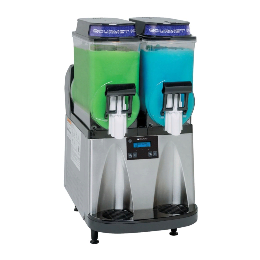
Bunn ULTRA-2 Installation & Operating Manual
Cold water dispenser
Hide thumbs
Also See for ULTRA-2:
- User manual ,
- Installation and operating manual (23 pages) ,
- Installation & operating manual (7 pages)

Related Manuals for Bunn ULTRA-2


Summary of Contents for Bunn ULTRA-2
- Page 1 ULTRA-2 INSTALLATION & OPERATING MANUAL BUNN-O-MATIC CORPORATION POST OFFICE BOX 3227 SPRINGFIELD, ILLINOIS 62708-3227 PHONE: (217) 529-6601 FAX: (217) 529-6644 www.bunnomatic.com 32080.0001B 12/05 ©2005 Bunn-O-Matic Corporation...
-
Page 2: Table Of Contents
Schematic Wiring Diagrams ..................31 BUNN-O-MATIC COMMERCIAL PRODUCT WARRANTY Bunn-O-Matic Corp. (“BUNN”) warrants equipment manufactured by it as follows: 1) All equipment other than as specified below: 2 years parts and 1 year labor. 2) Electronic circuit and/or control boards: parts and labor for 3 years. -
Page 3: User Notices
CAUTION – Improper electrical installation will damage components. An electrician must provide electrical service as specified below. Model ULTRA-2, This dispenser has an attached cordset and requires a 2-wire, grounded, individual branch circuit rated 120 volts ac, 15 amp, single phase, 60 Hz. The mating connector must be a NEMA 5-15R. -
Page 4: Initial Setup
INITIAL SETUP CAUTION – The dispenser is very heavy! Use care when lifting or moving it. Use at least two people to lift or move the dispenser. 6.0" MIN. 1. Set the dispenser on a sturdy counter top. The dispenser requires a minimum of 6.0" air clearance at the rear of the dispenser. - Page 5 INITIAL SETUP (CONT.) 9. Align the auger shaft with the 10. Install auger nose bushing into 11. Thoroughly rinse the hoppers flat fin of the auger. Push the inside front of hopper. and install them over the augers augers as far as they will go and and cooling drums.
-
Page 6: Operating Controls
OPERATING CONTROLS There are five of these switches that will be used for the operation of the dispenser. switch (upper left corner of the control pad) This switch is the ON/OFF toggle switch which powers up the dispenser and the LCD display. When ON the Date and Time toggle back and forth continously except during programming. -
Page 7: Programming
PROGRAMMING Using the menu-driven display on the front of the dispenser, the operator has the ability to alter or modify various parameters such as beverage consistency and set day/night “ON/OFF” times. The operator is also prompted to check a variety of periodic service functions or even a step-by-step cleaning routine. There is also the oppor- tunity to return all changes back to factory default settings. - Page 8 PROGRAMMING THE DISPENSER During normal operations, the Date, the Time, and the Serial Number toggle back and forth continuously. The following function screens are in the order they appear from the menu display. Each screen will have instructions and procedures to program the various functions of the dispenser. HOME SCREEN Displays the TIME, DATE, SERIAL NUMBER and ASSET NUMBER which toggle back and forth continuously.
- Page 9 MENU FUNCTION INDEX (Continued) TEST AUGERS ? SET THICKNESS ? CLEANING GUIDE ? SET LANGUAGE ? PASSWORD 0 SET DATE TIME ? NEXT PM COMPLETE ? DEFROST MINUTES SET NIGHT TIME YES THICK ADJUST DAY TO CLEAN OFF 6 MONTH PM NEXT NEXT 250 L REFILL 155...
- Page 10 Cleaning Guide This function leads the operator through a nine step cleaning process when answered YES (“ICE”). Depress GOURMET to display the next cleaning instruction. When entering this mode, the refrigeration system will automatically turn OFF. After step when hoppers are drained, the augers will turn OFF.
-
Page 11: Set Consistency
Set Consistency This function allows the operator to adjust the ice consistency, or torque of each auger when answered YES (“ICE”). Two screens will appear for left and right. The operator can scroll through a range of a minimum of 1 (ULTRA) to a maximum of 16 (ICE). -
Page 12: Test Augers
Test Augers This function tests the operation of forward and reverse of each auger motor. Left auger appears first. Press the ICE hidden switch to toggle between OFF, FORWARD and REVERSE. Press GOURMET hidden switch to repeat the operation for the right auger motor. A one minute time out will return to the Home Screen. LEFT AUGER TEST TEST AUGERS ? NEXT FORWARD... -
Page 13: Set Language
Password From this screen, the operator must know the password before moving on to the remaining functions. The range is from 0 - 9999 with the factory default being 0. PASSWORD NEXT Set Language ? (Late Model Dispensers) The setting of the Set Language mode allows the operator to scroll thru a list of languages stored in the software and select one for the display messages. - Page 14 Set Night Time/Set Day Time The setting of the Day/Night mode allows the dispenser to “power down” during off hours. The bottom corners displaying “ICE” will change to “CHILL” during the night mode. During the night mode, the product will be kept chilled to below 35°F.
- Page 15 Preventive Maintenance Complete? This function is used to reset a reminder message Preventive Maintenance Due every six months. The ma- chine will not shut down if service is not performed. When the service is performed and the message is answered YES (ICE), the time and date is recorded for another six months to elapse.
-
Page 16: Days To Clean
Day To Clean Off (formerly Days..Disabled) This function allows the operator to program a cleaning schedule from 1 to 14 days. The default screen is 0 or DISABLED. Selecting - or ULTRA will prompt the screen Days To Clean. Once a number of days is selected the screen will prompt two functions, CLEAN MESSAGE ONLY or CLEAN LOCKOUT. - Page 17 Consistency Adjust Lock This is an option of locking the Set Consistency function by selecting + (YES) or - (NO). NO THICK ADJUST YES THICK ADJUST NEXT NEXT 32080.0001 021105...
- Page 18 Switches Enabled This function allows the operator to lockout the touch pad. Selecting + (ON) provides no time delay on switches except for the center (GOURMET) hidden switch. Selecting - (LOCKOUT) provides a five second hold to wake up the touch pad and a two minute time frame from last button pressed to make adjustments before returning to sleep mode (five second hold).
- Page 19 Refill Threshold (Late Model Dispensers with Refill Kit Installed only) This function allows the operator to adjust the Refill Threshold depending on the type of product being dispensed. 250 R REFILL 155 250 L REFILL 155 (-) THRESHOLD (+) (-) THRESHOLD (+) TEST REFILL ? ACTIVATE VALVE LEFT DONE RIGHT...
-
Page 20: Ad Message Enabled
Ad Messages Enabled (Late Model Dispensers) This function allows the operator to create an AD Message that will toggle with the Home Screen messages. AD MESSAGE AD MESSAGE DISABLED ENABLED MODIFY MESSAGE ? SCROL THRU ALPHA (MESSAGE) NEXT-NEXT LETTER SCROL DONE NEXT SAVE ? AD MESSAGE EDIT... - Page 21 Enter Asset Number This is the function to set the asset number using a range of 0 to 999999 (the factory default is 0). It is used to track the usage or service of an individual machine within a group. ENTER ASSET # AN000000 Set Password...
-
Page 22: Restore Defaults
Restore Default? Answering YES (ICE) to this function returns the unit back to preset factory constants. 1. Set Consistency ? 10 2. Set Night Time - DISABLED 3. Set Day Time - DISABLED RESTORE DEFAULT ? 4. 6 Month PM - ENABLE 5. - Page 23 TEMP & TORQUE Press and hold for five seconds the ULTRA and ICE hidden switches to display the TEMP & TORQUE. The temperature of each cooling drum and the hot gas temperature will toggle back and forth. The auger torque is displayed continuously.
-
Page 24: Using The Dispenser For Granita-Type Products
Wait for the liquid to freeze to the desired consistency. HINTS – Bunn-O-Matic recommends that the product in the dispenser be thawed each day, usually overnight. The ice granules get too large and a consistent product is difficult to maintain if left frozen for an extended period of time. -
Page 25: Other Recommendations For Your Dispenser
OTHER RECOMMENDATIONS FOR YOUR DISPENSER • Whether liquid concentrate or granulated powder, all product must be thoroughly mixed BEFORE adding it to the hoppers. • For best results with granita-type products, use only products with an apparent brix of 12 or higher. Some products may work with an apparent brix as low as 9. -
Page 26: Recommended Daily Cleaning
RECOMMENDED DAILY CLEANING NOTE – Turn the power OFF to the dispenser before proceeding. 1. Empty all product from the hoppers. Disconnect the hopper lid lamp cords and remove the lids. 2. Depress the hopper lock 3. Pull forward to remove. Pull the auger from the cooling plunger. - Page 27 INSTALLATION 1. Install the seals over the flange 2. Align the auger shafts with the 3. Install auger nose bushing into at the rear of the cooling drums augers. Push the augers as far inside front of hopper. and press the seals firmly into as they will go and rotate them place as shown.
-
Page 28: Auto-Fill Cleaning Instructions
Auto-fill Cleaning Instructions (With Brixing Pump Installed) Materials required 1. Non-sudsing liquid detergent (such as common household automatic dishwasher liquid detergent). 2. Household bleach (Sodium chloride solution: 5.25%) or equivalent. 3. Clean five (5) gallon bucket. 4. Measuring Cup 5. An adaptor is needed to hold the Q.C.D. fitting on the concentrate suction line open. A connector from an empty bag will work. -
Page 29: Required Regular Maintenance
REQUIRED REGULAR MAINENANCE: Semi Annual: Bunn #34245.0000 is required to perform the semi annual Preventive maintenance: Note: Service caused by failure to perform required maintenance is not covered by warranty. The following instructions apply to one hopper only; Auger Motor Cover repeat each step for all hoppers. - Page 30 REQUIRED REGULAR MAINENANCE (Continued) 6. Pull the auger shaft assembly straight out of cooling drum. Open face of seal Inspect the shaft for abnormal wear. away from tool 7. From the front of dispenser, remove the seal and blue bushing from cooling drum and discard them.
-
Page 31: Schematic Wiring Diagrams
WHI-22 J6-1 COMPRESSOR ASSY BLK-22 CLOCK WHI/ORN COMPRESSOR MOTOR LIMIT THERM. t° t° t° 120 VOLTS AC LEFT RIGHT 2 WIRE TORQUE TORQUE SENSOR SENSOR LEFT RIGHT SINGLE PHASE 60 HZ ASSY 32082.0000B 01/02 © 2002 BUNN-O-MATIC CORPORATION 32080.0001 120105... - Page 32 CLOCK WHI/ORN COMPRESSOR MOTOR LIMIT THERM. t° t° t° 230 VOLTS AC LEFT RIGHT 2 WIRE TORQUE TORQUE SENSOR SENSOR LEFT RIGHT SINGLE PHASE 50 HZ ASSY 32082.0001B 05/02 © 2002 BUNN-O-MATIC CORPORATION CIRCUIT BOARD TRANSFORMER WHI/BLU WHI/BLK 32080.0001 120105...
- Page 33 J2-5 COMPRESSOR LEFT RIGHT MOTOR LEVEL LEVEL LIMIT THERM. PROBE PROBE J2-10 LEFT RIGHT J1-14 J12-14 TORQUE TORQUE LEFT RIGHT SENSOR SENSOR 120 VOLTS AC 2 WIRE ASSY SINGLE PHASE 60 HZ 32082.0002A 01/05 © 2005 BUNN-O-MATIC CORPORATION 32080.0001 120105...
- Page 34 COMPRESSOR PROBE PROBE MOTOR LIMIT THERM. J2-10 J1-14 J12-14 LEFT RIGHT 230 VOLTS AC TORQUE TORQUE 2 WIRE SENSOR SENSOR LEFT RIGHT SINGLE PHASE ASSY 50 HZ 32082.0003A 01/05 © 2005 BUNN-O-MATIC CORPORATION CIRCUIT BOARD TRANSFORMER WHI/BLU WHI/BLK 32080.0001 120105...
Need help?
Do you have a question about the ULTRA-2 and is the answer not in the manual?
Questions and answers