Table of Contents
Advertisement
Quick Links
Download this manual
See also:
User Manual
Advertisement
Table of Contents

Related Manuals for Planet FGSW-2620CS


Summary of Contents for Planet FGSW-2620CS
- Page 1 User's Manual FGSW-2620CS 24-Port 10/100Mbps with 2 Gigabit TP / SFP Combo Web Smart Switch - 1 -...
-
Page 2: Fcc Warning
Trademarks Copyright © PLANET Technology Corp. 2011. Contents subject to revision without prior notice. PLANET is a registered trademark of PLANET Technology Corp. All other trademarks belong to their respective owners. Disclaimer PLANET Technology does not warrant that the hardware will work properly in all environments and applications, and makes no warranty and representation, either implied or expressed, with respect to the quality, performance, merchantability, or fitness for a particular purpose. -
Page 3: Table Of Contents
User’s Manual of FGSW-2620CS TABLE OF CONTENTS 1. INTRODUCTION ................5 1.1 C ..............................5 HECKLIST 1.2 A ........................... 5 BOUT THE WITCH 1.3 F ..............................6 EATURES 1.4 S ............................8 PECIFICATION 2. HARDWARE DESCRIPTION ............10 2.1 F ............................ - Page 4 User’s Manual of FGSW-2620CS 4.6 Q ............................51 ETTING 4.6.1 Priority Mode ........................... 52 4.6.2 Class of Service Configuration......................53 4.6.3 TCP / UDP Port Based QoS ......................55 4.7 S ............................. 57 ECURITY ILTER 4.7.1 MAC Address Filter......................... 58 4.7.2 TCP / UDP Filter ..........................
-
Page 5: Introduction
In the following section, the term “Web Smart Switch” means the Switch device, ie. FGSW-2620CS; term of “switch” can be any third switches. -
Page 6: Features
User’s Manual of FGSW-2620CS 1.3 Features Complies with the IEEE 802.3, IEEE 802.3u, IEEE 802.3ab, IEEE 802.3z Gigabit Ethernet standard ◆ 24-Port 10/100Mbps Fast Ethernet ports ◆ 2 10/100/1000Mbps ports share with 2 SFP ports ◆ Each Switching ports support auto-negotiation-10/20, 100/200Mbps (Fast Ethernet) , 1000/2000Mbps (Gigabit ◆... - Page 7 User’s Manual of FGSW-2620CS 19-inch rack mount size ◆ Internal full-range power supply suitable for worldwide use ◆ EMI standards complies with FCC, CE class A ◆ ◆ - 7 -...
-
Page 8: Specification
User’s Manual of FGSW-2620CS 1.4 Specification Model FGSW-2620CS Hardware Specification Ports 24 10/100Base-TX RJ-45 Auto-MDI/MDI-X interfaces Gigabit Ports 2 10/100/1000Mbps ports share with 2 SFP interfaces Switch Processing Scheme Store-and-Forward Throughput (packet per second) 6.54Mpps@64Bytes Switch Fabric 8.8Gbps Address Table... - Page 9 User’s Manual of FGSW-2620CS IGMP Snooping v1 / v2 Allow to disable or enable. Standards Conformance Regulation Compliance FCC Part 15 Class A, CE IEEE 802.3 (Ethernet) IEEE 802.3u (Fast Ethernet) IEEE 802.3ab (Gigabit Ethernet) IEEE 802.3z (Gigabit Ethernet) Standards Compliance IEEE 802.3x (Full-duplex flow control)
-
Page 10: Hardware Description
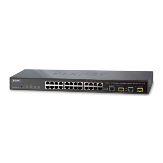
2 Gigabit TP/SFP combo ports either can be 1000Base-T for 10/100/1000Mbps or 1000Base-SX/LX through SFP (Small Factor Pluggable) interface. The LED Indicators are also located on the front panel of the Web Smart Switch. Figure 2-1: FGSW-2620CS Switch front panel 2.1.1 LED Indicators System... -
Page 11: Rear Panel
The rear panel of the Web Smart Switch indicates an AC inlet power socket, which accepts input power from 100 to 240VAC, 50-60Hz, 0.5A. Figure 2-2: FGSW-2620CS Switch rear panel Power Notice: 1. The device is a power-required device, it means, it will not work till it is powered. If your networks should active all the time, please consider using UPS (Uninterrupted Power Supply) for your device. - Page 12 User’s Manual of FGSW-2620CS Step 5: Supply power to the Web Smart Switch. Connect one end of the power cable to the Web Smart Switch. Connect the power plug of the power cable to a standard wall outlet then power on the Web Smart Switch.
- Page 13 User’s Manual of FGSW-2620CS Figure 2-4 Mounting the Web Smart Switch in a Rack Step 6: Precede with the steps 4 and steps 5 of section 2.3.1 Desktop Installation to connect the network cabling and supply power to your Web Smart Switch.
- Page 14 User’s Manual of FGSW-2620CS Approved PLANET SFP Transceivers PLANET Web Smart Switch supports both single mode and multi mode SFP transceiver. The following list of approved PLANET SFP transceivers is correct at the time of publication: ■MGB-SX SFP (1000Base-SX SFP transceiver ) ■MGB-LX SFP (1000Base-LX SFP transceiver )
- Page 15 User’s Manual of FGSW-2620CS Figure 2-6 Pull out the SFP transceiver Never pull out the module without pull the handle or the push bolts on the module. Direct pull out the module with violent could damage the module and SFP module slot of the Web Smart Switch.
-
Page 16: Switch Management
User can manage the Web Smart Switch by Web Management via a network connection. 3.2.1 Web Management The PLANET FGSW-2620CS provide a built-in browser interface. You can manage the Switch remotely by having a re- mote host with Web browser, such as Microsoft Internet Explorer, Netscape Navigator or Mozilla Firefox. - Page 17 User’s Manual of FGSW-2620CS The following install instructions guiding you for run the Planet Smart Discovery Utility. 1. Deposit the Planet Smart Discovery Utility in administrator PC. 2. Run this utility and the following screen appears. Figure 3-1 Planet Smart Discovery Utility Screen If there are two LAN cards or above in the same administrator PC, choose different LAN card by use the “Select Adapter”...
-
Page 18: Logging On To The Fgsw-2620Cs
7. Press “Exit” button to shutdown the planet Smart Discovery Utility. 3.3 Logging on to the FGSW-2620CS When you log on to the Web Smart Switch Web interface for the first time, a sign-on string appears and you are prompted for a Web login username and password. -
Page 19: Web Management
User’s Manual of FGSW-2620CS 4. WEB MANAGEMENT To modify your PC’s IP domain to the same with Web Smart Switch then use the default IP address (192.168.0.100) to remote configure Web Smart Switch through the Web interface. 4.1 Login in to the Switch To access the Web-browser interface you must first enter the user name and password, the default user name and password is "admin”. -
Page 20: System
User’s Manual of FGSW-2620CS The seven items and it description shown as below: ◆ System: Provide System configuration of Web Smart Switch. Explained in section 4.2. Port Management: Provide Port Management configuration of Web Smart Switch. Explained in section 4.3. -
Page 21: System Information
User’s Manual of FGSW-2620CS Object Description System Information Display the MAC address, Hardware Version, and Software Version, Device Description. plained in section 4.2.1. IP Configuration Allow to change the IP subnet address of Web Smart Switch. Explained in section 4.2.2. -
Page 22: Ip Configuration
User’s Manual of FGSW-2620CS • System Up Time The period of time the device has been operational. • Idle Time Security Set idle time and behavior. Table 4-2 Descriptions of the System Information Web Page Screen Objects 4.2.2 IP Configuration... -
Page 23: Password Setting
User’s Manual of FGSW-2620CS 4.2.3 Password Setting This section provides change the Username and Password, the screen in Figure 4-6 appears. Figure 4-6 Password Setting Web Page Screen The page includes the following fields: Object Description Username Displays the user name. -
Page 24: Firmware Update
User’s Manual of FGSW-2620CS 4.2.5 Firmware Update This section provides firmware upgrade of the Web Smart Switch, the screen in Figure 4-9 appears. Figure 4-9 Firmware Update Web Page Screen Press “Update” button for start the firmware upgrade process, the screen in Figure 4-10 &... -
Page 25: Reboot
User’s Manual of FGSW-2620CS Figure 4-14 Firmware Update Web Page Screen 1. Recommend to use IE 7.0 or FireFox browser tools for firmware upgrade process. 2. Firmware upgrade needs several minutes. Please wait a while, and don’t power off the Web Smart Switch until the update progress is complete. -
Page 26: Port Management
User’s Manual of FGSW-2620CS 4.3 Port Management This section provides Port Configuration, Port Mirroring, Bandwidth Control, Broadcast Storm Control and Port Statistics from Web Smart Switch, the screen in Figure 4-16 appears and Table 4-5 describes the system object of Web Smart Switch. -
Page 27: Port Configuration
User’s Manual of FGSW-2620CS 4.3.1 Port Configuration This section introduces detail settings of per port on Web Smart Switch; the screen in Figure 4-17 appears and Table 4-6 descriptions the Port Configuration objects of Web Smart Switch. Figure 4-17 Port Configuration Web Page Screen... - Page 28 User’s Manual of FGSW-2620CS The page includes the following fields: Object Description • Port Allow choosing all or one port of Web Smart Switch for further man- agement, the available options is All & 01 to 26. • Speed Mode...
-
Page 29: Port Mirroring
User’s Manual of FGSW-2620CS 4.3.2 Port Mirroring This section introduces detail settings of Port Mirroring function of Web Smart Switch; the screen in Figure 4-18 appears Table 4-7 descriptions the Port Mirroring objects of Web Smart Switch. Figure 4-18 Port Mirroring Web Page Screen... -
Page 30: Bandwidth Control
User’s Manual of FGSW-2620CS 4.3.3 Bandwidth Control This section introduces detail settings of Bandwidth Control function of Web Smart Switch; the screen in Figure 4-19 appears and Table 4-8 description the Bandwidth Control objects of Web Smart Switch. Figure 4-19 Bandwidth Control Web Page Screen... -
Page 31: Broadcast Storm Control
User’s Manual of FGSW-2620CS 4.3.4 Broadcast Storm Control This section introduces detail settings of Broadcast Storm Control function of Web Smart Switch; the screen in Figure 4-20 appears and Table 4-9 descriptions the Broadcast Storm Control objects of Web Smart Switch. - Page 32 User’s Manual of FGSW-2620CS The page includes the following fields: Object Description • Counter Mode Se- Provide different type of Ethernet traffic counter mode, the available op- tions are shown as below: lection Receive Packet & Transmit Packet collision Count & Transmit Packet Drop Packet &...
-
Page 33: Vlan Setting
User’s Manual of FGSW-2620CS 4.4 VLAN Setting A Virtual LAN (VLAN) is a logical network grouping that limits the broadcast domain. It allows you to isolate network traffic so only members of the VLAN receive traffic from the same VLAN members. Basically, creating a VLAN from a switch is logically equivalent of reconnecting a group of network devices to another Layer 2 switch. - Page 34 User’s Manual of FGSW-2620CS 802.1Q Tag User Priority VLAN ID (VID) 3 bits 1 bits 12 bits TPID (Tag Protocol Identifier) TCI (Tag Control Information) 2 bytes 2 bytes Destination Source Ad- Ethernet Preamble VLAN TAG Data Address dress Type...
- Page 35 User’s Manual of FGSW-2620CS Default VLANs The Switch initially configures one VLAN, VID = 1, called "default." The factory default setting assigns all ports on the Switch to the "default". As new VLAN are configured in Port-based mode, their respective member ports are removed from the "default."...
-
Page 36: 802.1Q Vlan
User’s Manual of FGSW-2620CS 4.4.1 802.1Q VLAN This section introduces detail information of IEEE 802.1Q VLAN function of Web Smart Switch; Choose “802.1Q VLAN” from VLAN from the VLAN Mode and press “Apply” button to enable the 802.1Q VLAN function. The screen in Figure 4-23 &... - Page 37 User’s Manual of FGSW-2620CS • Group Display the existence 802.1Q VLAN groups. • VID Display different VLAN ID from multi-802.1Q VLAN groups. • VLAN Name Assign and display different VLAN name from multi-802.1Q VLAN groups. Up to maximum 8 characters allow.
- Page 38 User’s Manual of FGSW-2620CS Figure 4-25 802.1Q VLAN Per Port Setting Web Page Screen This section introduces detail information of IEEE 802.1Q VLAN Per Port Setting of Web Smart Switch; The Table 4-13 description the 802.1Q VLAN Per Port Setting objects of Web Smart Switch.
-
Page 39: 802.1Q Vlan Setting Example
User’s Manual of FGSW-2620CS The page includes the following fields: Object Description • Port Indicate port 1 to port 26. • Link Type Define UnTag or Tag on each port of Web Smart Switch. Default mode is “UnTag”. • Uplink Define No Uplink or Uplink on each port of Web Smart Switch. - Page 40 User’s Manual of FGSW-2620CS While [PC-1] transmit an untagged packet enters Port-1, the Web Smart Switch will tag it with a VLAN Tag=2. [PC-2] and [PC-3] will received the packet through Port-2 and Port-3. [PC-4], [PC-5] and [PC-6] received no packet.
- Page 41 User’s Manual of FGSW-2620CS Figure 4-27 Assign VLAN members for VLAN 2 and VLAN 3 Please remember to remove the Port 1 – Port 6 from VLAN 1 membership, since the Port 1 – Port 6 had been assigned to VLAN 2 and VLAN 3.
- Page 42 User’s Manual of FGSW-2620CS Figure 4-28 Remove specify ports from VLAN 1 member Its import to remove the VLAN member port from VLAN 1 group. Or the ports would become overlapping setting. Assign PVID for each port: Port-1,Port-2 and Port-3 : PVID=2.
- Page 43 User’s Manual of FGSW-2620CS Figure 4-29 Port 1-Port 6 802.1Q VLAN Configuration Two separate 802.1Q VLAN with overlapping area scenario Based on the two separate VLAN group examples above, VLAN 2 and VLAN 3 member port cannot see each other.
- Page 44 User’s Manual of FGSW-2620CS Figure 4-31 VLAN overlap port setting Define a VLAN 1 as a “Public Area” that overlapping with both VLAN 2 members and VLAN 3 members. - 44 -...
- Page 45 User’s Manual of FGSW-2620CS Figure 4-32 VLAN 1 – The public area member assign Setup Port-7 with “PVID=1” at VLAN Per Port Configuration page. The screen in Figure 4-33 appears. Figure 4-33 Setup Port-7 with PVID-1 - 45 -...
-
Page 46: Port Based Vlan
User’s Manual of FGSW-2620CS Although the VLAN 2 members: Port-1 to Port-3 and VLAN 3 members: Port-4 to Port-6 also belongs to VLAN 1. But with different PVID settings, packets form VLAN 2 or VLAN 3 is not able to access to the other VLAN. -
Page 47: Port Based Vlan Setting Example
User’s Manual of FGSW-2620CS The page includes the following fields: Object Description • VID Display different VLAN ID from multi-port based VLAN groups. • VLAN Name Assign and display different VLAN name from multi-port based VLAN groups. Up to maximum 8 characters allow. - Page 48 User’s Manual of FGSW-2620CS The page includes the following fields: Object Description • MTU Port Indicate the MTU Port of Web Smart Switch. • Member Port Indicate the Member Port of Web Smart Switch. • Apply Button Press this button for save current configuration of Web Smart Switch.
-
Page 49: Trunk
User’s Manual of FGSW-2620CS 4.5 Trunk Port link aggregations can be used to increase the bandwidth of a network connection or to ensure fault recovery. Link aggregation lets you group up to 4 consecutive ports into a single dedicated connection between any two the Switch or other Layer 2 switches. -
Page 50: System Priority
User’s Manual of FGSW-2620CS Trunk Setting This function allows to configuring the trunk function. It provides up to two trunk groups and each trunk group provides 4 member ports. Also provide four various Trunk Hash Algorithm policies for selection. The screen in... -
Page 51: Qos Setting
User’s Manual of FGSW-2620CS Default link group 3 is included P25, P26. • State Allow disable or enable port trunk from Web Smart Switch, the available options are Enable and Disable. Default mode is Disable. • Type Allow to selects port trunk type from Web Smart Switch, the available options are LACP and Static. -
Page 52: Priority Mode
User’s Manual of FGSW-2620CS The page includes the following fields: Object Description • Priority Mode Provide three different Priority polices on Web Smart Switch. Explained in section 4.6.1. • Class of Service Provide three different polices on each port of Web Smart Switch. -
Page 53: Class Of Service Configuration
User’s Manual of FGSW-2620CS 4.6.2 Class of Service Configuration This section introduces detail information of Class of Service Configuration of Web Smart Switch; the screen in Figure 4-40 appears and Table 4-20 descriptions the Class of Service Configuration of Web Smart Switch. - Page 54 User’s Manual of FGSW-2620CS VLAN Priority tag value define IEEE 802.1p priority value from VLAN tag High Priority User priority values= 4~7 Low Priority User priority values= 0~3 IP TOS/DSCP Priority value define TOS/DSCP Value AF11 AF21 AF31 AF41 High Priority...
-
Page 55: Tcp / Udp Port Based Qos
User’s Manual of FGSW-2620CS 4.6.3 TCP / UDP Port Based QoS This section introduces detail information of TCP / UDP Port Based QoS Configuration of Web Smart Switch; the screen in Figure 4-41 appears and Table 4-21 descriptions the TCP / UDP Port Based QoS Configuration of Web Smart Switch. - Page 56 User’s Manual of FGSW-2620CS The page includes the following fields: Object Description • Protocol Display different Protocol for define the QoS policy in option • FTP(20,21) Provide F-I-F-O, Discard, Low, High options. • SSH(22) Provide F-I-F-O, Discard, Low, High options.
-
Page 57: Security Filter
User’s Manual of FGSW-2620CS 4.7 Security Filter This function provides Security Filter of Web Smart Switch; the screen in Figure 4-42 appears and Table 4-22 descriptions the Security Filter of Web Smart Switch. Figure 4-42 Security Filter Web Page Screen... -
Page 58: Mac Address Filter
User’s Manual of FGSW-2620CS 4.7.1 MAC Address Filter This section introduces detail information of MAC Address Filter of Web Smart Switch; the screen in Figure 4-43 appears Table 4-23 descriptions the MAC Address Filter of Web Smart Switch. Figure 4-43 MAC Address Filter Web Page Screen... -
Page 59: Tcp / Udp Filter
User’s Manual of FGSW-2620CS The page includes the following fields: Object Description • MAC Address Allow to input three MAC Address on per port of Web Smart Switch. • Select Port Allow to select port 1 to port 26. • Binding Allow to Disable or Enable the binding function on each port of Web Smart Switch. - Page 60 User’s Manual of FGSW-2620CS The page includes the following fields: Object Description • Function Enable Allow to Disable or Enable the TCP / UDP Filter function. Default mode is Disable. • Port Filtering Rule Allow to Forward or Block the Port Filtering Rule. Default mode is Block.
-
Page 61: Spanning Tree
User’s Manual of FGSW-2620CS 4.8 Spanning Tree This function provides Spanning Tree of Web Smart Switch; the screen in Figure 4-45 appears and Table 4-25 descriptions the Spanning Tree of Web Smart Switch. Figure 4-45 Spanning Tree Web Page Screen... -
Page 62: Stp Bridge Settings
User’s Manual of FGSW-2620CS 4.8.1 STP Bridge Settings This section introduces detail information of STP Bridge Settings of Web Smart Switch; the screen in Figure 4-46 appears Table 4-26 descriptions the STP Bridge Settings Configuration of Web Smart Switch. Figure 4-46 STP Bridge Settings Web Page Screen... - Page 63 User’s Manual of FGSW-2620CS Enter a value between 6 through 40. • Forward Delay The number of seconds a port waits before changing from its Rapid Spanning-Tree Protocol learning and listening states to the forwarding state. Enter a value between 4 through 30.
-
Page 64: Stp Port Settings
User’s Manual of FGSW-2620CS 4.8.2 STP Port Settings This section introduces detail information of STP Port Settings of Web Smart Switch; the screen in Figure 4-47 appears Table 4-27 descriptions the STP Port Settings Configuration of Web Smart Switch. Figure 4-47 STP Port Settings Web Page Screen... - Page 65 User’s Manual of FGSW-2620CS The page includes the following fields: Object Description • Port No. Allow choosing one port of Web Smart Switch for further management, the available options is 01 to 26. • Priority (0~240) Decide which port should be blocked by setting its priority as the lowest.
-
Page 66: Loopback Detection Settings
User’s Manual of FGSW-2620CS 4.8.3 Loopback Detection Settings This section introduces detail information of Loopback Detection Settings of Web Smart Switch; the screen in Figure 4-48 appears and Table 4-28 descriptions the Loopback Detection Settings Configuration of Web Smart Switch. - Page 67 User’s Manual of FGSW-2620CS The page includes the following fields: Object Description • Loopback Detect Allow to Disable or Enable the Loopback Detect Function. Default mode is Disable. Function • Auto Wake Up Allow to Disable or Enable the Auto Wake Up function. Default mode is Disable.
-
Page 68: Dhcp Relay Agent
User’s Manual of FGSW-2620CS 4.9 DHCP Relay Agent This function provides DHCP Relay Agent of Web Smart Switch; the screen in Figure 4-49 appears and Table 4-29 scriptions the DHCP Relay Agent of Web Smart Switch. Figure 4-49 DHCP Relay Agent Web Page Screen... -
Page 69: Dhcp Relay Agent
User’s Manual of FGSW-2620CS 4.9.1 DHCP Relay Agent This section introduces detail information of DHCP Relay Agent of Web Smart Switch; the screen in Figure 4-50 appears Table 4-30 descriptions the STP Bridge Settings Configuration of Web Smart Switch. Figure 4-50 DHCP Relay Agent Web Page Screen... -
Page 70: Vlan Map Relay Agent
User’s Manual of FGSW-2620CS The page includes the following fields: Object Description • DHCP Server IP Assign the DHCP Server IP address. Table 4-31 Descriptions of the STP Bridge Settings Configuration Screen Objects 4.9.3 VLAN MAP Relay Agent This section introduces detail information of VLAN MAP Relay Agent of Web Smart Switch; the screen in... -
Page 71: Misc Operation
User’s Manual of FGSW-2620CS 4.10 Misc Operation This function provides Misc Operation of Web Smart Switch; the screen in Figure 4-53 appears and Table 4-33 descrip- tions the Misc Operation of Web Smart Switch. Figure 4-53 Misc Operation Web Page Screen... -
Page 72: Backup/Recovery
User’s Manual of FGSW-2620CS 4.11 Backup/Recovery This function provides Backup/Recovery of Web Smart Switch; the screen in Figure 4-54 appears and Table 4-34 scriptions the Backup/Recovery of Web Smart Switch. Figure 4-54 Backup/Recovery Web Page Screen The page includes the following fields:... -
Page 73: Snmp Settings
User’s Manual of FGSW-2620CS 4.12 SNMP Settings This function provides SNMP Settings of Web Smart Switch; the screen in Figure 4-55 appears and Table 4-35 descrip- tions the SNMP Settings of Web Smart Switch. Figure 4-55 SNMP Settings Web Page Screen... -
Page 74: Logout
User’s Manual of FGSW-2620CS 4.13 Logout This section provide Web logout function on Web Smart Switch, after choose this function and the following screen ap- pears in Figure 4-56. Please press “Logout” button to take effect and Login Web Screen appears. Please re-login the Web Smart Switch for further management. -
Page 75: Switch Operation
User’s Manual of FGSW-2620CS 5. SWITCH OPERATION 5.1 Address Table The Switch is implemented with an address table. This address table composed of many entries. Each entry is used to store the address information of some node in network, including MAC address, port no, etc. This information comes from the learning process of Ethernet Switch. -
Page 76: Auto-Negotiation
User’s Manual of FGSW-2620CS 5.5 Auto-Negotiation The STP ports on the Switch have built-in "Auto-negotiation". This technology automatically sets the best possible bandwidth when a connection is established with another network device (usually at Power On or Reset). This is done by detect the modes and speeds at the second of both device is connected and capable of, both 10Base-T and 100Base-TX devices can connect with the port in either Half- or Full-Duplex mode. -
Page 77: Troubleshooting
Check the LNK/ACT LED on the switch Try another port on the Switch Make sure the cable is installed properly Make sure the cable is the right type Turn off the power. After a while, turn on power again. How to deal forgotten password situation of FGSW-1820CS / FGSW-2620CS? Solution:... -
Page 78: Appendix A Networking Connection
User’s Manual of FGSW-2620CS APPENDIX A NETWORKING CONNECTION A.1 Switch‘s RJ-45 Pin Assignments 1000Mbps, 1000Base T RJ-45 Connector pin assignment Contact MDI-X BI_DA+ BI_DB+ BI_DA- BI_DB- BI_DB+ BI_DA+ BI_DC+ BI_DD+ BI_DC- BI_DD- BI_DB- BI_DA- BI_DD+ BI_DC+ BI_DD- BI_DC- 10/100Mbps, 10/100Base-TX... - Page 79 User’s Manual of FGSW-2620CS The standard RJ-45 receptacle/connector There are 8 wires on a standard UTP/STP cable and each wire is color-coded. The following shows the pin allocation and color of straight cable and crossover cable connection: Straight Cable SIDE 1...
-
Page 80: Ec Declaration Of Conformity
*Model Number: FGSW-2620CS * Produced by: Manufacturer‘s Name : Planet Technology Corp. Manufacturer‘s Address: 10F., No.96, Minquan Rd., Xindian Dist., New Taipei City 231, Taiwan (R.O.C.) is herewith confirmed to comply with the requirements set out in the Council Directive on the Approximation of the Laws of the Member States relating to Electromagnetic Compatibility Directive on (89/336/EEC).
Need help?
Do you have a question about the FGSW-2620CS and is the answer not in the manual?
Questions and answers