Advertisement
Model F-14
Model F-85
Model F-1725
This manual is considered to be part of the appliance and is to be given to the OWNER or
MANAGER of the restaurant, or to the person responsible for TRAINING OPERATORS of
this appliance. Additional manuals are available from your WELLS DEALER.
THIS MANUAL MUST BE READ AND UNDERSTOOD BY ALL PERSONS USING OR
INSTALLING THIS APPLIANCE. Contact your WELLS DEALER if you have any
questions concerning installation, operation or maintenance of this equipment.
2M-307588
p/n
Rev. C
WELLS BLOOMFIELD, LLC
10 Sunnen Drive P.O.Box 430195
St. Louis, MO
telephone: 314-781-2777
fax: 314-781-2714
www.wellsbloomfield.com
IMPORTANT: DO NOT DISCARD THIS MANUAL
PRINTED IN UNITED STATES OF AMERICA
63143 USA
OWNERS MANUAL
COUNTERTOP
Model F-55
EXPLODED VIEW
WIRING DIAGRAM
STANDARD
FRYERS
MODELS
F-14
F-49
F-55
F-67
F-85
F-1725
Includes
INSTALLATION
USE & CARE
PARTS LIST
09
M301
0127 cps
301
Advertisement
Table of Contents

Related Manuals for Wells F-14


Summary of Contents for Wells F-14
-
Page 1: Exploded View
Additional manuals are available from your WELLS DEALER. THIS MANUAL MUST BE READ AND UNDERSTOOD BY ALL PERSONS USING OR INSTALLING THIS APPLIANCE. Contact your WELLS DEALER if you have any questions concerning installation, operation or maintenance of this equipment. - Page 2 The for information and other details concerning warranty. prices charged by Wells Bloomfield for its products are SERVICE POLICY AND PROCEDURE GUIDE and ADDITIONAL WARRANTY EXCLUSIONS Resetting of safety thermostats, circuit breakers, over cleaning schedules, are customer responsibility.
- Page 3 PARTS & SERVICE CUSTOMER SERVICE DATA INTRODUCTION Thank You for purchasing this Wells Bloomfield appliance. Proper installation, professional operation and consistent maintenance of this appliance will ensure that it gives you the very best performance and a long, economical service life.
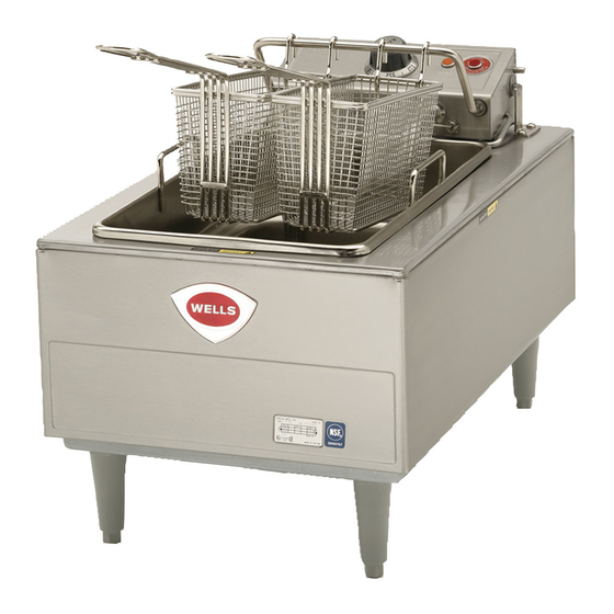
- Page 4 FEATURES & OPERATING CONTROLS Fig. 1 Countertop Fryer Features & Operating Controls F-55 Shown - Others are Similar...
- Page 5 PRECAUTIONS AND GENERAL INFORMATION DANGER: SEVERE BURN HAZARD Contact with hot oil will cause severe burns. Always wear protective clothing and heat resistant gloves when operating the fryer or filtering the oil. WARNING: ELECTRIC SHOCK HAZARD All servicing requiring access to non-insulated components must be performed by qualified service personnel.
-
Page 6: Agency Listing Information
Local and NFPA codes. COMPONENTS 1 or 2 ea. FRYPOT 2 or 4 ea. FRY BASKETS 4 ea. ADJUSTABLE LEGS (except F-14) 4 ea. RUBBER FEET (F-14 only) SETUP Setup the appliance only on a firm, level, non-combustible surface. Verify local codes for requirements. Concrete, tile, terrazzo or metal surfaces are recommended. - Page 7 DO NOT open any access panel which requires the use of tools. Failure to follow this warning can result in severe electrical shock. F-14 and F-49 FRYER ELECTRICAL INSTALLATION CAUTION: RISK OF This fryer is equipped with a cord and plug, and requires a properly DAMAGE installed matching receptacle.
- Page 8 SUPPORT ROD, then carefully lowering the elements. 2. Fill the FRYPOT with commercial-grade liquid shortening to the MIN OIL line. Capacity: F-14 14 pounds F-49, F-55 15 pounds F-67, F-85 30 pounds (15 pounds per frypot) IMPORTANT: DO NOT overfill the frypot. Cold oil will expand as it heats.
- Page 9 CLEANING INSTRUCTIONS DANGER: BURN HAZARD Contact with hot oil will cause severe burns. Allow the fryer to cool before cleaning. Always wear protective clothing and heat resistant gloves when cleaning the fryer. PREPARATION CAUTION: Turn temperature control to OFF Allow fryer to cool completely before cleaning ELECTRIC Unplug fryer from receptacle before cleaning SHOCK HAZARD...
-
Page 10: Disposal Of Used Oil
DISPOSAL OF USED OIL DANGER: BURN HAZARD Contact with hot oil will cause severe burns. Allow the fryer to cool before cleaning. Always wear protective clothing and heat resistant gloves when handling hot oil. PREPARATION CAUTION: Turn temperature control to OFF Allow fryer to cool completely before draining BURN HAZARD FREQUENCY... -
Page 11: Troubleshooting Suggestions
Set to desired temperature desired temperature Fryer will not heat Hi-limit safety tripped Clean element , reset hi-limit Contact Wells Authorized Service Damaged internal component Agency for repairs Temperature control thermostat thermobulb contaminated with Clean element Fryer will not maintain... - Page 12 MAINTENANCE Periodic cleaning is PERIODIC CLEANING necessary to remove Add 1/2 cup of granulated dishwasher detergent to frypot. Fill with water carbonization from the to the MAX OIL line. elements and frypot. Lower the element into the frypot and set the control knob to 225ºF Frypot may be cleaned by Boil the mixture for five minutes.
- Page 13 EXPLODED VIEW & PARTS LIST F-14 COUNTERTOP 14# FRYER 65061 (120V 51157 58656 5-15P 20141 (240V hi-limit 6-30P 58667 54066 50516 amber 55736 (pk 10) 50133 KEPS green temp control 65788 (120V) 65777 58667 50789 (240V) 55637 65725 65783 (120V) kit: handle &...
- Page 14 EXPLODED VIEW & PARTS LIST F-49 COUNTERTOP SINGLE-HEAD FRYER 50177 fiber washer 54066 50176 (pk 10) lock washer 50133 50172 HEAD ASSY COMPLETE, F-49 temp control 62899 (208V) 50516 amber 62900 (240V) 51157 63665 50157 58656 (pk 10) hi-limit 20161 50157 1/2 size 20162...
- Page 15 EXPLODED VIEW & PARTS LIST F-55 COUNTERTOP SINGLE-HEAD FRYER 50177 fiber washer 55511 50176 (pk 10) lock washer HEAD ASSY COMPLETE, F-55 50172 55510 62903 (208V) temp control 50516 amber 62904 (240V) 51157 50157 58656 hi-limit 20161 62504 1/2 size (pk 4) 20162 50157...
- Page 16 EXPLODED VIEW & PARTS LIST F-67 COUNTERTOP DUAL-HEAD FRYER - FRY HEAD COMPONENTS HEAD ASSY COMPLETE, F-67 62915 (208V) NOTE: Unit has two identical 62916 (240V) fryer heads. Only one is shown 54066 50177 fibre washer 50176 (pk 10 ) lock washer 50133 temp control 50172...
- Page 17 EXPLODED VIEW & PARTS LIST F-67 COUNTERTOP DUAL-HEAD FRYER - CABINET COMPONENTS 20161 half-size 20162 full-size 53890 (pk 10) (typical) 51717 (pk 40) 20169 52806 53245 53895 center pivot 53068 54005 50131 61947 (pk 10) 55736 (pk 10) green KEPS 50183 51053 (pk 100)
- Page 18 EXPLODED VIEW & PARTS LIST F-85 - COUNTERTOP DUAL-HEAD FRYER - FRY HEAD COMPONENTS HEAD ASSY COMPLETE, F-85 62903 (208V) NOTE: Unit has two identical 62904 (240V) fryer heads. Only one is shown 55511 50177 fibre washer 50176 (pk 10 ) lock washer 55510 temp control 50172...
- Page 19 EXPLODED VIEW & PARTS LIST F-85 - COUNTERTOP DUAL-HEAD FRYER - CABINET COMPONENTS 20161 half-size 20162 20169 full-size 53890 (pk 10) 53245 50183 51717 (pk 40) 52806 53895 center pivot 50131 50183 61974 end pivot (pk 10) 51053 (pk 100) 55736 green KEPS (pk 10)
- Page 20 EXPLODED VIEW & PARTS LIST F-1725 - COUNTERTOP MULTI-ELEMENT SINGLE-HEAD FRYER HEAD ASSEMBLY COMPONENTS 54452 50516 amber 51157 54665 52428 51208 58656 51207 (pk 4) 58687 54666 58667 50147 54662 58665 55566 (pk 100) 58661 (208V) 58751 58662 (240V) 3 places 55511 58718 6 places...
- Page 21 EXPLODED VIEW & PARTS LIST F-1725 - COUNTERTOP MULTI-ELEMENT SINGLE-HEAD FRYER CABINET COMPONENTS 50183 53890 (pk 10) 52806 20820 51717 (pk 40) 53068 62850 54005 20537 50131 20519 61974 (pk 10) 55736 green KEPS (pk 10) 52704 57779 (208V) 57780 (240V) 53860 54748 53848...
-
Page 22: Wiring Diagram
WIRE NUT TEMP SIGNAL LITE LITE HEATING ELEMENT FRYER F-14 AMPS VOLTS 1 PHASE (50/60 HZ) 15.0 16.3 18.8 WIRING DIAGRAM F-14 p/n 307306 POWER CORD RELAY CONTROL HI-LIMIT THERMOSTAT THERMO WIRE NUT COIL HI-LIMIT THERMO WIRE NUT WIRE NUT TEMP... - Page 23 WIRING DIAGRAM TERMINAL BLOCK REMOVE JUMPER WHEN EXTERNAL CONTROL USED IMPORTANT: DO NOT CONNECT ANY POWER TO FLAME SENSOR TERMINAL BLOCK TERMINAL BLOCK FLAME SENSOR CONTROL THERMOSTAT RELAY HI-LIMIT THERMO COIL HI-LIMIT THERMO WIRE NUT WIRE NUT TEMP SIGNAL LITE LITE HEATING ELEMENT...
- Page 24 WIRING DIAGRAM TERMINAL BLOCK TERMINAL BLOCK (3 PHASE) (1 PHASE) CONTROL CONTROL THERMOSTAT THERMOSTAT RELAY RELAY HI-LIMIT HI-LIMIT HI-LIMIT THERMO HI-LIMIT THERMO THERMO THERMO COIL COIL WIRE WIRE WIRE WIRE SIGNAL TEMP TEMP SIGNAL LITE LITE LITE LITE FRYER F-67 and F-676 HEATING HEATING ELEMENT...
- Page 25 WIRING DIAGRAM *REMOVE JUMPER WHEN TEMP LIGHT TEMP LIGHT TROUBLE TROUBLE EXTERNAL CONTROL IS (AMBER) (AMBER) LIGHT (RED) LIGHT (RED) USED. LEFT RIGHT IMPORTANT: HEATING HEATING DO NOT CONNECT ANY ELEMENT ELEMENT POWER TO FLAME SENSOR TERMINAL CONTROL CONTROL BLOCK! THERMOSTAT THERMOSTAT HI-LIMIT...
- Page 26 WIRING DIAGRAM...
-
Page 27: Customer Service Data
PARTS & SERVICE DESCRIPTION PART NO. IMPORTANT: Use only factory authorized service parts and replacement FRY BASKET, HALF-SIZE, ALL EXC. F-14 and F-1725 20161 filters. FRY BASKET, FULL SIZE 20162 For factory authorized FRYPOT, ALL EXCEPT F-1725 20169 service, or to order factory... - Page 28 Commercial Food Equipment Service Association Wells Bloomfield proudly supports CFESA Commercial Food Equipment Service Association SERVICE TRAINING - QUALITY SERVICE SERVICE TRAINING - QUALITY SERVICE Genuine Parts Protect - YOU - All - Ways CUSTOMER SATISFACTION CUSTOMER SATISFACTION WELLS BLOOMFIELD, LLC 10 Sunnen Drive P.O.Box 430195...
Need help?
Do you have a question about the F-14 and is the answer not in the manual?
Questions and answers