Table of Contents
Advertisement
Advertisement
Table of Contents

Related Manuals for Hi Sharp Digital video recorder


Summary of Contents for Hi Sharp Digital video recorder
- Page 1 Digital Video Recorder User’s Manual...
-
Page 2: Table Of Contents
Contents Index 1. DVR I/O Connection …………………………………………………… 2. DVR Operation ………………………………………………………… 3. DVR Function Setup …………………………………………………… 3.1 System Setup ………………………………………………………… 3.2 Network ……………………………………………………………… 3.3 Device ………………………………………………………………… 3.4 Record ………………………………………………………………… 3.5 Event ………………………………………………………………… 4. Search & Playback ……………………………………………………… 5. Remote Connection ……………………………………………………… 5.1 Remote Function Setup ……………………………………………... -
Page 3: Dvr I/O Connection
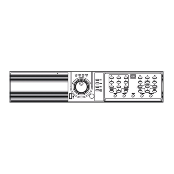
1. DVR I / O Connection The DVR system front panel with different Type device Type A : 4 CH DVR Type B : 9 CH DVR Type C : 16 CH DVR... - Page 4 Power: DVR power On / Off button Type A doesn’t offers this power button REC: Record button PLAY: Playback button SEQ.: Channel sequence Split screen select 0 ~ 9: Channel select Zoom: Live zoom x 2 FREEZE: Live image freeze MENU: To main OSD setup Setup:...
- Page 5 System rear connection detail 1) Video Source Connection It connects video sources (camera image) to BNC connector via cable. 2) LOOP OUT Connection BNC connector of LOOP OUT can be used other device’s input. 1. It may cause low quality of picture when connecting cable from any device to LOOP OUT BNC.
- Page 6 6) RS232 port Connection. RS232 port is connected to PC and other devices for specific function and After Sales purpose. 7) USB port Connection front rear It consists of 1 USB (Front), 1 USB (Rear), its supported devices are such as USB mouse, USB external HDD and USB memory stick Type A support 4 Alarm in .
- Page 7 10) Factory Reset Switch and NTSC/PAL Shift Switch NTSC/PAL Shift Switch Type A doesn’t offers this Factory reset function Factory Reset Switch The factory reset switch located at the left side of NTSC/PAL switch is used to return to factory default setup values.
-
Page 8: Dvr Operation
2. DVR Operation System Power On • Power on the DVR. It takes about 100 seconds to boot (It may take more when network cable isn’t connected) System Shutdown • Press “Power” button in front panel to shutdown the DVR system . or [SETUP Menu] ->... - Page 9 Installation Guide for HDD & ODD devices (SATA Type 4CH) Description 1. ODD(CD-RW/DVD-RW) devices should be installed as “SATA 4”. 2. HDD for system needs to be installed as “SATA 1”. MAIN BOARD SATA 1 : HDD#1 SATA 2 : HDD#2 SATA 4 : ODD(CD/DVD) Guide Chart for installing several HDDs ODD(CD-RW/DVD-RW)
- Page 10 Installation Guide for HDD & ODD devices (SATA Type 16CH) Description 1. ODD(CD-RW/DVD-RW) devices should be installed as “SATA 4”. 2. HDD for system needs to be installed as “SATA 1”. SATA 1 : HDD#1 SATA 2 : HDD#2 SATA 3 : HDD#3 SATA 4 : ODD(CD/DVD) Guide Chart for installing several HDDs ODD(CD-RW/DVD-RW)
- Page 11 Monitoring Screen Monitoring screen : it monitors each channel. <Screen Indication> Upper-Left : Camera Name P – Pan/tilt (PTZ dome control) A – Audio Upper-Right : Record mode (Blue-Normal, Red-Event) Motion status Central : Video Loss, Hidden Camera Status Bar : DVR status Indication (Backup, HDD usage, Current Time, SEQUENCE, FREEZE, Login info.
- Page 12 Screen Split Use mouse press DISPLAY button to change screen display with 1 -> 4 -> 9 -> 16 by turn Direct Channel 1) Press channel No. on the remote control or front panel. 2) Click the screen to watch specific channel using mouse. ** Pressing No.1 button responds a bit delayed to wait a possible signal input of No.10~16 (approx 2.5 seconds) LOG IN...
- Page 13 Menu Bar * Click MENU button or right button of mouse DISPLAY Type A -> 1, 4 Split screen change Type B -> 1, 4, 9 Split screen change Type C -> 1, 4, 9, 16 Split screen change MISCELLANUEOUS SEQUENCE Sequence camera group regularly FREEZE...
- Page 14 SPOT 2 spot monitors are supported and sequence / fix mode can be selected. Select the Spot monitor in SETUP>DEVICE>SPOT MONITOR. Notice Type A device only support 1 spot outp No OSD indication of camera number for SPOT output. Pan Tilt/Zoom/Focus/Iris Preset setting and moving functions are supported. Each function can be different from each PTZ protocol.
- Page 15 STATUS RECORD Displays current recording status EVENT Displays current event information (motion/alarm). DISK Displays current Disk information NETWORK Displays current network information. Also displays current connected client information.
- Page 16 PANIC RECORD Set recording mode in an emergency situation. Press REC button in front panel or use mouse to enable Panic record . SETUP Select to enter SETUP menu CAMERA COLOR Changes camera screen color Changes OSD (On Screen Display's position. SEARCH Select to enter into SEARCH menu...
- Page 17 BACKUP Use USB device to backup . 1) Backup Device Search 4) Warning when data size is over 5) Copy data to USB device 2) Select USB device to backup 3) Calculate data size 6) Backup to USB completed It would block remote search during local backup procedure. If users use defective media to backup, it might cause system reset...
- Page 18 Note : After backup to USB device , use windows Media Player to play the AVI file , if your Media Player can’t shows any video , it should be the codec problem , you have to visit the Xvix web site , http://www.xvid.org to download the Xvid codec and install to your computer .
-
Page 19: Dvr Function Setup
3. DVR Function Setup 3.1 System Setup SYSTEM Set up various system related items. INFORMATION DATE/TIME DISK USER LOGOUT SYSTEM SHUTDOWN **It takes more than 10 seconds to initialize log... - Page 20 INFORMATION INFORMATION DEVICE NAME: User can change the DVR name on his own. LANGUAGE : Select language. VERSION : Shows S/W version info. (With UPGRADE button, you can upgrade the newest S/W version) Contact manufacturer or distributors for more Upgraded version . CONFIGURATION IMPORT : Import the backup configuration file on USB device , use this function user can setup other DVR with same configuration .
- Page 21 DATE/TIME DATE/TIME Set date, time & Time zone of System. When you use it for the first time Set these items in advance . It takes more than 50 seconds to validate time setting.
- Page 22 TIME SYN Synchronize time with internet time server. Default time zone is GMT Set the GMT on the DATE/TIME list and Adjust TIME SYNC. NTP server function is only for DVR client HOLIDAY In the schedule record setup , it automatically converts normal date to holiday schedule.
- Page 23 DISK DISK TABLE Shows current disk information connected to system. IMPORTED : DISK installed RECORD : RECORD possible SYSTEM : DISK allocated for SYSTEM FORMAT ALL Format all connected HDD disks. (When you select info column of connected DISK separately, You can format DISK one by one).
- Page 24 USER USER Shows currently registered user lists. User accounts can be added or deleted. add account with this button. X Delete account with this button. USER ADD Possible to add user account according to authority. CONFIRM LOGIN When YES selected, LOGIN needs to be confirmed every time to enter into setup / system menu.
- Page 25 Shows all log infos on SYSTEM and other events CLEAR : Remove all log info. UP/DOWN button : Move to next/previous log info page by page . Move to first part of LOG info. Move to Last part of LOG info. ▲...
-
Page 26: Network
3.2 Network NETWORK Set up various NETWORK items DDNS E-MAIL CALLBACK NAS POLICY NAS DISK... - Page 27 MAX CONNECTION Shows maximum numbers of Connectable users. (Up to 7) DHCP TYPE Default TYPE is DHCP Select during automatic DHCP IP. User set DNS only. (under the situation of DHCP server operating mode) STATIC TYPE Select STATIC IP. All setting values of IP, GATEWAY, NETMASK Need to be set manually.
- Page 28 DDNS(DYNAMIC DNS) ENABLE Select if you want DDNS This is under the situation of Dynamic IP Network. SERVER Select DDNS server EZDDNS : Specialized DDNS server operated by server DYNDNS: DDNS common server In order to use DDNS service Account & HOSTNAME should be registered in the server first. HOSTNAME User name of IP ADDRESS ON Dynamic IP circumstance.
- Page 29 E-MAIL ENABLE Select when you need E-MAIL transmission. ALL event information is sent to admin’s E-mails. SMTP SERVER Write the MAIL sending SMTP server name. AUTH ENABLE Check when you need account authority. ID / PASSWORD Input account & password .
- Page 30 CALLBACK ENABLE Check to use CALLBACK function . All event or specific information are sent to “Agent” Program which is installed on P.C CALLBACK ADD Register IP address of P.C for callback function...
- Page 31 NAS POLICY ENABLE Check to use NAS function . NAS POLICY Select All option means copy all H.D.D Record data to NAS device . Select Current option means copy H.D.D Now record data to NAS device. NAS DISK ADD NAS DISK Input NAS Address, ID and Password Ex: NAS Address:...
- Page 32 NAS Storage function description NAS storage keeps recorded data more long than local storage and this is main purpose of this development. This covers the limitation of local DVR system and save data safely through network connected mass storage. - Local DVR performs search data on NAS but no transferring available to Client viewer neither backup to ODD, USB from NAS.
-
Page 33: Device
3.3 Device DEVICE These are item lists for the control of CAMERA, ALARM . CAMERA ALARM DISPLAY MAIN MONITOR SPOT MONITOR MISCELLANEOUS... - Page 34 CAMERA TITLE Can change the camera name. HIDDEN Doesn’t show the screen on live mode Even though it records and runs normally. PTZ ENABLE Check if you want to use PTZ function. PTZ PROTOCOL Select PTZ PROTOCOL. Various of protocol information including PELCO-D are implemented.
- Page 35 ALARM ENABLE Check if you use specific ALARM. TITLE Changes connected ALARM names. ALARM TYPE Select specific ALARM TYPE. (NORMAL OPEN, NORMAL CLOSE) DISPLAY Shows all OSD display details. CAMERA INFOMATION Selects the display of CAMERA NO, TITLE EVENT INFOMATION Select OSD display for the EVENT.
- Page 36 MAIN MONITOR Set up SEQUENCE, EVENT POPUP of main monitor. SEQUENCE Set up the screen switching times. EVENT POPUP Check if you want event pop up function. Select VGA output resolution:800x600, 1024x768, 1280x1024. SPOT MONITOR Set up functions of SPOT MONITOR. SPOT NUMBER Select SPOT output numbers.
- Page 37 MISCELLANEOUS Control of remote controller/key related functions. KEY TONE ENABLE Select button volume on the front panel. CK101 /CK201 Mapping Table Use CK101/CK201 to control this DVR system FULL CK101/201 Key DVR FUN FULL ALARM CK101/201 Key ZOOM FRZE DVR FUN SPOT ZOOM FREEZE...
-
Page 38: Record
3.4 Record These are control lists of recording related functions. RECORD POLICY RECORD... - Page 39 RECORD POLICY Select RECORD types. -Two types (Single Record, Overwrite) -Default Record Policy is Overwrite If we change record policy from overwrite to single when hard disk is full. It won't stop record immediately. It would stop after current record block is finished. It might be few minutes later ENABLE RECORD Select record status.
- Page 40 Recording Frame rate in different device type as below table (NTSC Mode) Type A Type B Type C ( 4CH ) ( 9CH ) ( 16CH ) 120 FPS 120 FPS 120 FPS Half-D1 120 FPS 240 FPS 240 FPS 120 FPS 270 FPS 480 FPS...
-
Page 41: Event
3.5 Event EVENT This is for the control of all event items such as MOTION, SENSOR. MOTION SENSOR VIDEO LOSS SYSTEM... - Page 42 MOTION SETUP Click mouse right button or MENU KEY Set up the MOTION area & sensitivity. button to see motion area window RECORD Set pre& post record mode. When record frames are less, PRE/POST RECORD need to be set a lot more for correct record search.
- Page 43 SENSOR SETUP Set the SENSOR name & TYPE. NORMAL OPEN : Normally it opens and sends signals when detects sensors. NORMAL CLOSE : Normally it closes, and it sends SIGNAL when detects sensors. RECORD Set Connecting camera, Pre / Post record. When record frames are less, PRE/POST RECORD need to be set a lot more for correct record search.
- Page 44 VIDEO LOSS VIDEO LOSS can be an event type and can set camera record and action. RECORD Set connecting camera Pre& post record. When record frames are less, PRE/POST RECORD need to be set a lot more for correct record search. ACTION Setting up list for how to act after EVENT.
- Page 45 SYSTEM Sets how to operate event related with DISK mainly. DISK FULL Set up when HDD is full of record. DISK ERROR Sets when there is an error on HDD. S.M.A.R.T Enables the system to prevent possible malfunction of HDD by interfacing between system and HDD.
-
Page 46: Search & Playback
4. Search & Playback Playback Screen : Record Playback Playback Time : Playback Time Display Display Status Playback Icon Pause (Ⅱ) Playback (▶) Multiple Playback(▶ ▶, ▶ ▶ ▶, ▶ ▶ ▶ ▶) ▶, ▶ ▶, ▶ ▶ ▶ , fast frame-playback ) Advanced Playback( It randomly shows the first searched record file when it goes to SEARCH MODE. - Page 47 SEARCH MENU DISPLAY Select screen division mode. Type A -> (1,4 split) , Type B -> (1,4 , 9 split) Type C -> (1,4 , 9 ,16 split) SEARCH KEY (Front panel key) STOP : Exit Playback (Return to Live Display) BACK STEP : Calendar Search STEP : Event Search REW : Move to the first...
- Page 48 EVENT SEARCH It shows all EVENT record list. Use mouse click related EVENT, It plays that event promptly. It may not be the same channel image as shown on EVENT LIST because it shows the first display image recorded at that time zone. SEARCH KEY Can be selectable on EVENT search.
- Page 49 FIRST Move to first part of recorded data. LAST Move to last part of recorded data. BOOKMARK Sets automatically starting time during back up. It is useful to set a bookmark as starting time of backup . For example : in playback mode , press BOOKMARK to set the backup start time and press BACKUP to set the backup end time .
- Page 50 SEARCH DEVICE Search internal or external SYSTEM DISK . LOCAL DEVICE Search the data of internal DISK. BACKUP DEVICE Search backup device (Select when you play the backup data.) If there are various back up devices , you can select a specific one . It supports DVD +R/-R /CD RW and USB device for backup NAS DEVICE Search backup device from NAS device via network access, please check the NAS setup is correct in...
-
Page 51: Remote Connection
5. Remote Connection <REMOTE CONNECTION > With connected to DVR remotely, it is to perform Remote Monitoring, Remote Search, Remote Backup etc. (Please install remote program from the program CD) Environment conditions for Remote Program 1. INTEL P-4 2. 256M or higher main memory(512M recommend) 3. - Page 52 Remote Control : Use Windows IE Browser User can use Windows IE Browser connected to the remote DVR system . If the viewer opens on IE, user needs to put connection IP on Select Internet Options Security Trusted sites ADD this website to the zone IE Browser will display DVR control center, Login with ID and Password , then you can control the DVR system through the IE Browser .
- Page 53 Connection information and Button Shows DVR’s name, IP address and connection status. DVR connection button. : Enter IP address and user authentication to connect DVR : Modify IP address and user authentication Edit of the existing list Delete : Delete existing use. <DVR Connection Window>...
- Page 54 <What is IP address ?> A set of address system that is used to find out destination in network access via Internet or LAN. IP address is divided into REAL IP and VIRTUAL IP, and REAL IP must be sent on DVR for the access from remote site via internet.
- Page 55 Language : To choose program’s language. Video Display : YUV mode : According to your PC graphic card ability, the support can be decided. This mode shows faster, clear ability of image transmission than RGB mode. RGB mode : It is widely compatible with most graphic cards, and select this when YUV mode is not supported..
- Page 56 <Recording Status> Shows and check the recording status <Event Status> Shows DVR’s event status and you can check the status of Motion, Sensor, Video Loss at real time. <Alarm Control> You can On/Off the DVR’s alarm if you press the Alarm control button. <HDD Status>...
-
Page 57: Remote Function Setup
5.1 Remote Function Setup Remote Set Up <Camera> Select Camera No. Title : Item to revise/type the camera name. Covert Camera (Hidden) : When checked, The camera will be hidden Linked PTZ : Sets up PTZ camera. Enable PTZ : Enable PTZ function . Name :Item to check PTZ Camera’s model name. - Page 58 Remote Setup <Alarm> Alarm No : Item to select Alarm No. To set up all the camera equally, Choose “select all” Enable Alarm : Item to select to use Alarm, Removing the check stops using that channel. Title : Item to type Alarm’s name. Type : Item to select Alarm’s type.
- Page 59 Remote Setup <Main Monitor> Sequence Dwell : Setup Main-monitor sequence dwell time. Popup Event : Enable Popup Event function or not. VGA Resolution : Select Main-monitor with VGA output resolution.
- Page 60 Remote Setup <Spot Monitor> Spot Number: Select Spot output channel from ch1~2. Enable Spot Sequence : Enable Spot sequence function or not. Fixed Camera : Select Spot output source from ch1~16. Sequence Dwell: Select Spot sequence dwell time. Sequence Camera: Select Spot sequence camera channel.
- Page 61 Remote Set Up <Record> Camera No : Item to select Camera No. To set up all the camera equally, Choose “select all” Resolution : Item to change the resolution. - NTSC : 720X480, 720X240, 360X240 - PAL : 720X576, 720X288, 360X288 Record Mode : No Record / Normal Record / Event Record / N + E / Schedule Record Normal Record Frame :Item to select normal record frame.
- Page 62 <Schedule Record > 1. Select the Record Mode 2.Select Day/Time < Schedule Record> It is the list of selection in which schedule to Schedule Indication by color use in operating the relevant camera channel. Normal(N) : (Blue) First select the item you need among Normal time, Event and Normal time + Event.
- Page 63 Remote Set Up <Record Policy> Record Policy: Item to select record policy Record Enable : Enable /Disable Record . Policy : Single Record -> Stop recording on 100% of HDD capacity. Overwrite -> When HDD is fully , it will overwrite old data . Record Data Retention: Enable Data record retention function, setup range from 1~365 days.
- Page 64 Remote Set Up <Motion> Camera No : Item to select Camera No. To set up all the camera equally, Choose “select all” Enable : Selects to use motion sensor, Removing the check stops using that channel. Sensitivity : Adjusts the sensitivity in motion detection. There are 5 steps and as the number increase, it gets more sensitive.
- Page 65 Remote Set Up <Motion (Link Record)> Link Camera : Selects which channel to record when motion is detected on the relevant channel. ※ Multiple selection possible Pre Record : Sets pre-event recording time. (Max 5 second) Post Record : Sets post-event recording time. (Max 60 second) Remote Set Up <Motion (Link Action)>...
- Page 66 Remote Set Up <Sensor> Sensor No : Sets sensor No. To set up all the camera equally, Choose “select all” Enable Sensor : Selects to use sensor, Removing the check stop using relevant sensor. Sensor Name : Item to select sensor’s name. Sensor Type : Item to select sensor type.
- Page 67 Remote Set Up <Sensor (Link Record)> Link Camera : Selects which channel to record when sensor is detected on the relevant channel. ※ Multiple selection possible Pre Record : Sets up pre recording time. (Max 5 second) Post Record : Sets up post recording time. (Max 60 second) Remote Set Up <Sensor (Link Action)>...
- Page 68 Remote Set Up <Video Loss> Camera No : Item to select camera No. To set up all the camera equally, Choose “select all” Default enable the video loss...
- Page 69 Remote Set Up <Video Loss( Link Record)> Link Camera : Selects which channel to record when video loss is detected on the relevant channel. ※ Multiple selection possible Pre Record : Sets up pre recording time. (Max 5 second) Post Record : Sets up post recording time. (Max 60 second) Remote Set Up <Video Loss (Link Action)>...
- Page 70 Remote Set Up <System> DISK FULL : List for all installed HDD disks. Enable Disk Full Notice : Activate Disk Full Notice when installed disks are full. Remote Set Up <Disk Full (Link Action)> Popup Camera : Not available as of now Popup Time : Not available as of now Link Alarm :...
- Page 71 Mail : When all installed HDD disks are full, the log is sent to the selected e-mail Callback : When HDDs are full, the log is sent to the selected IP address. Log : Selects to save Log writing when installed HDDs are full. (It is not recorded on the system Log, but used for event search.) SMART Enable SMART : Select to use SMART feature.
- Page 72 Remote Set Up <Network> DDNS: Enable DDNS service function. E-mail:Enable E-mail report function.
- Page 73 Callback:Enable callback alarm function. LAN:Select network connect type.
- Page 74 PLAY & PAUSE Starts or stops image transmission on the Remote Live screen. This starts automatically when search or set in the setup menu. Starts to play when pressed. Stops to play when pressed. AUDIO Transmission Controls Audio volume. ※Audio signal is sent on full screen mode only. Sound volume control gauge Mute Button : Stops audio transmission.
- Page 75 Channel Button Selected channel with full screen display , it has the same function as double click the left mouse button on the selected channel. <Type A > <Type B > <Type C > Type A -> CH 1~ 4 , other channels are not available Type B ->...
- Page 76 PTZ Operation PTZ Control Function Direction Button : Button to move top, bottom, left, right Channel Indication : Indicate current channel Speed Control Button : Button to control moving speed Image Control Button : Button to adjust Zoom, Focus, Iris Preset move button Preset save button Preset Move: Move to saved preset No.
-
Page 77: Remote Search & Playback
5.2 Remote Search & Playback Playback Display Camera Name Green Border Line : Display the selected camera. Recorded Date/Time SECTION Selects section Section is created when Date/Time is changed to former times. Former Date/Time will be kept in section 0. Newly set Date/Time will be kept in section 1……... - Page 78 Move & Event Search Time Search Button : Go to selected time Event Search Button : Popup the event search window Shows start and end time of recorded data. Go to the time to search and press OK button. <Time Search Window> Select the time to event search Select events in detail.
- Page 79 Connection Information and Button Shows DVR’s name, IP address and connection status. Open backup file play button Connect / Disconnect DVR Button When many DVRs are registered in the DVR list, each DVR can be remotely searched without closing The Remote Program. The linked list s can’t be edited <Connection List Window>...
- Page 80 Screen Division Button Screen Division Button AUDIO Play Controls audio volume. ※Audio signal is sent only on one full screen. Sound volume control gauge Mute Button : Stops audio transmission Image Control Button Brightness Brightness adjustment button : Contrast Adjusts the brightness of playing images. Blurring Sharpness Contrast adjustment button :...
- Page 81 Saving Button BackUp : Backup the searched image as Backup compressed image file. Print Print : Saving Image file Print the searched images. Saving AVI file Saving Image File : Saves the searched images as Image File. (Save JPEG format ) Saving AVI File : Saves the searched images as AVI file.
- Page 82 Preview : Preview of the images to print, which is printed with various information written on the bottom of the image. <Preview Window> Image Format : JPEG Format Saving Path : Selects the path to backup. <Image Save Window>...
- Page 83 Saving Information Selects camera No and start/end time to save. Including : Selects audio to include. Backup Path : Selects the path to backup Total Capacity : Shows total capacity Remaining Capacity : Shows remaining capacity <AVI Save Window> Check “Caption option” of Media Player to display time/date of playing AVI file. Right Mouse Click Action When the right button is clicked, the following menu below appears and the following functions can be used...
- Page 84 Time Table Selects year/month/day and hour/minute to search the recorded data. Year/Month Select Button : Button to move previous and next month. Recorded Date (Blue) : Shows recorded date in blue. Current Date (Blue Round) : Shows current date in blue round. No Recorded Date (Black) : Shows no recorded data in black.
- Page 85 Open Backup file to Playback Open Backup file Button : Click to slect backup file to playback Backup playback can play a data of Image file. Windows Media Player can play a data of AVI image files .
-
Page 86: Player Function
6. Player Function Play screen Camera Name Green border line : Display the selected camera. Recorded Time/Date Starting/End Move to starting record data Move to end of record data Play Progress Bar... - Page 87 Play button Fast Forward Fast Rewind Stop Play / Pause Sound volume Control Button ※Audio signal is sent only on one full screen. Sound volume control gauge Mute Button : Stops audio transmission Layout Button Layout button : Button to select screen division mode .
- Page 88 Open File / Program Info Information : Shows program information. <Program Info Window> Call Function Button : Button to call in the back up file. Select the backup data to play Backup playback can play a data of Image file. Windows Media Player can play a data of AVI image files .
-
Page 89: Cms Function Setup
7. CMS Function Setup CMS Program execution Login When program is first executed, Please input User ID and Password Default – ID: admin , Password: 1. - Page 90 CMS Main screen Function button User Management Add, edit, delete of CMS account. ≫Add : add CMS user ≫Edit : edit user ID, PASSWORD ≫Delete: delete user...
- Page 91 ▣ CMS System Requirements Win 2000 / Win XP / Win Vista / Win 7 INTEL P-4 2.4Ghz or over(recommendsP-4 3Ghz,over ) Main Memory 512MByte or over (recommends 1Gbyte,over) 64M over supports RGB (recommends 128Mbyte Video Memory over) Resolution 1024*768 over LAN Card 10/100 Supporting card Protocol...
- Page 92 User name : Type the user name authorized in DVR Password: Type the password authorized in DVR User Description: Shows the user information <Use management add/modify > Option management Language : To choose program’ language. Video output : ATI YUV mode : According to your PC graphic card ability, the support can be decided.
- Page 93 Group management Add, modify and delete a group in DVR : Add a group information Add… : Modify a group information Edit ... : Delete existing group information. Delete Group name : Specify a group name in DVR Group Description : Specify a group information ※...
- Page 94 DVR Management Add /modify/Delete DVR connection in the CMS : Enter IP address and user authentication to connect DVR Edit : Modify IP address and user authentication of the existing list Delete : Delete existing use. DVR name: Specify a name that you can easily identify.
- Page 95 VIEW Management Adds, edits, deletes Live/ E-map showed in CMS : add View information Add… : edit View information Edit... : delete View information Delete View name : put in any name for user to know easy Type : select LIVE or MAP Map file : In case the View is map, select to be used image...
- Page 96 Program Information Available to run the Log Viewer of the version and updated Information on CMS. Log Viewer By CMS, it makes the log of time, IP address, connecting port and status on connecting system. Program Exit It exits CMS.
- Page 97 DVR Tree All Connection It connects all DVRs nominated on the DVR information. All Disconnection It disconnects all DVRs connected on the DVR information. Group Indication of the Group of the DVR Indication of disconnect DVR Indication of connect DVR Camera Making the camera icons enabled, on connected with the DVR.
- Page 98 Main Screen Live Screen Channel name Recording Status DVR name Current time Pop-up menu on clicking the right button of mouse, •Stop : Temporary stops the current image of live view. •Close: Close the live channel screen . •Saving Image file : Saving the current live view . •Print: Printing out the current live view.
- Page 99 Chapter II PTZ Disabled PTZ Enabled On clicking the PTZ button, the PTZ control panel appears. If the selected camera has the disabled setting of PTZ, it will be disabled status like No.1pic. If not, it will be enabled status like No.2pic. Preset Movement It makes the preset moved to the selected area.
- Page 100 Chapter II E-Map Camera connected with DVR Live view of selected camera Sensor Detection of DVR Motion detection of the camera connected with DVR Camera disconnected with DVR It makes other maps connected (Map Link)
- Page 101 Usage of Dual Monitor On clicking the right button of mouse on the E-map tab, the pop-up appears. Dual monitor movement On the dual monitor function, the selected map is moved to the second monitor. Event pop-up On detecting motion, Pop-up automatically. Event sound On detecting event, the sound (that is set up on the option) happens.
Need help?
Do you have a question about the Digital video recorder and is the answer not in the manual?
Questions and answers